In-situ observation system combining laser light scattering and microscope under the shear field

A technology of laser light scattering and shear field, which is applied in the measurement of scattering characteristics, the use of stable shear force to test the strength of materials, fluorescence/phosphorescence, etc., which can solve the discomfort, no microscope part, and the inability to directly observe large-scale structures and other issues to achieve high-precision results

Inactive Publication Date: 2007-05-23
INST OF CHEM CHINESE ACAD OF SCI
View PDF0 Cites 3 Cited by
  • Summary
  • Abstract
  • Description
  • Claims
  • Application Information

AI Technical Summary

Problems solved by technology

The Hashimoto research group of Kyoto University in Japan built an instrument for laboratory use (K.Matsuzaka and T.Hashimoto.Rev.Sci.Instrum.70, 2387, 1999), which has the following technical problems: there is no microscope part, a

Method used


Image

  • In-situ observation system combining laser light scattering and microscope under the shear field
  • In-situ observation system combining laser light scattering and microscope under the shear field
  • In-situ observation system combining laser light scattering and microscope under the shear field

Examples


Embodiment 1

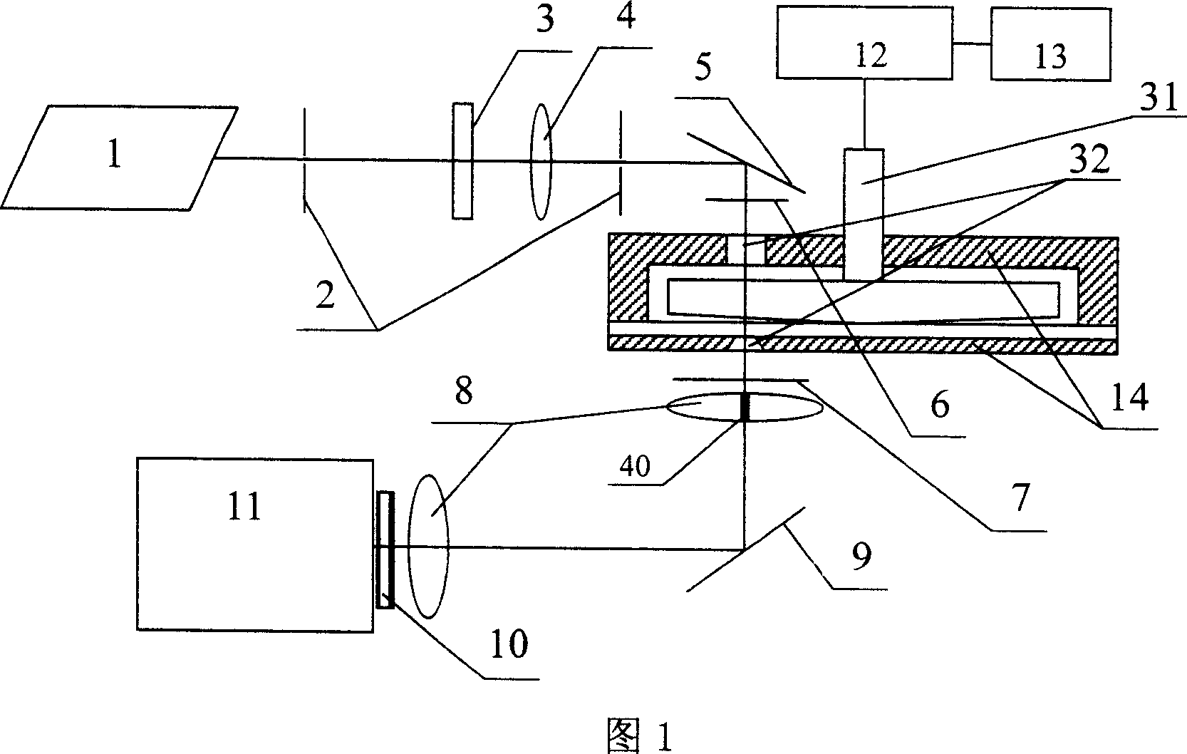
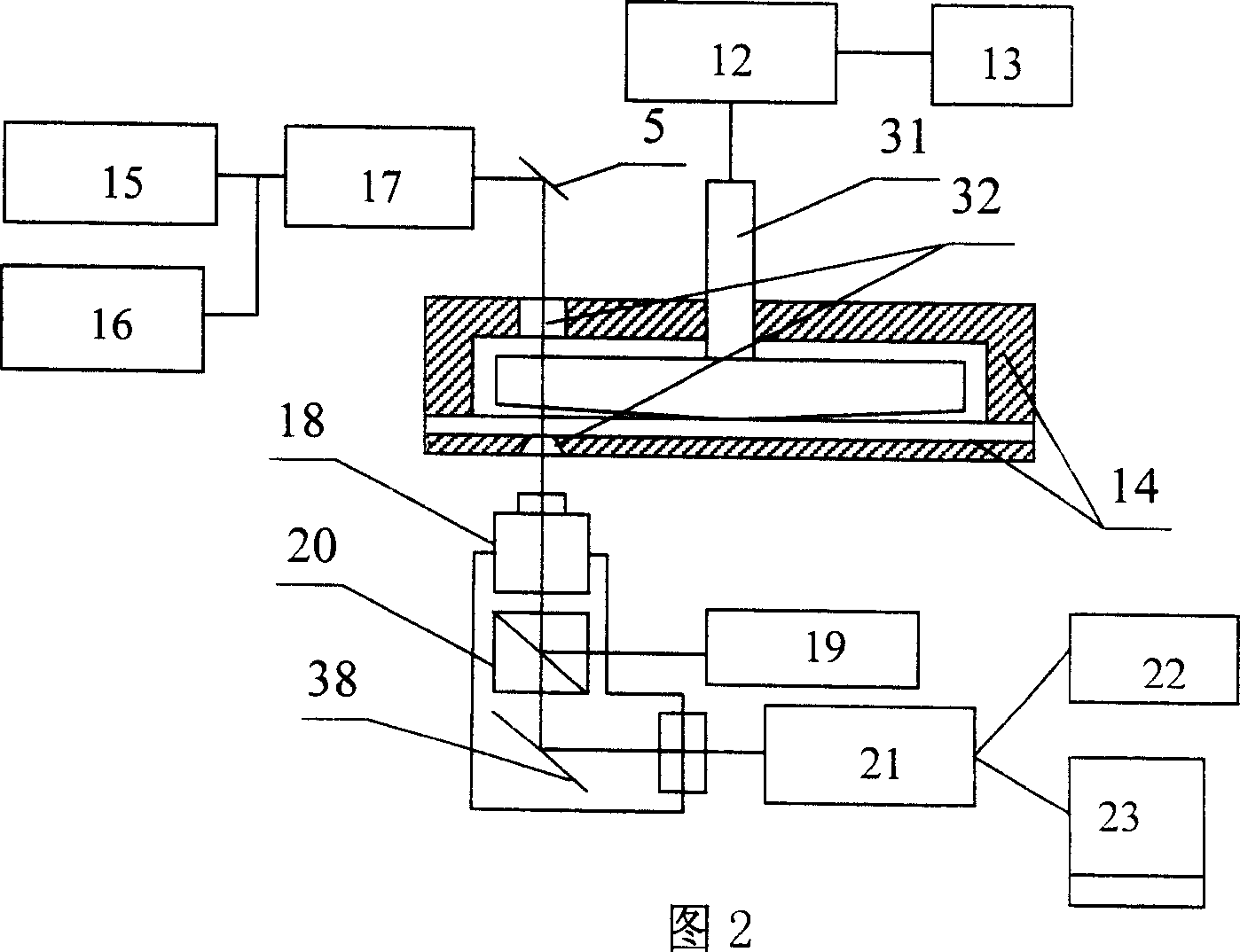
[0060] See Figure 4. The present invention includes a laser light scattering and microscope system, a sample pool 14 with a heater on a platform 36 shared by the two systems, a precise and controllable shear field applying device and a total reflection coating mirror 5 .

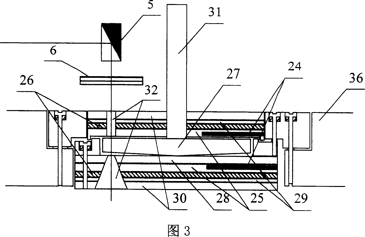
[0061] The power application device 12 driven by a micro-stepping motor and the controller 13 that constitute an accurate and controllable shear field application device are installed on the platform 36, and the controller 13 is connected with a computer through a data line; the power application device driven by a micro-stepping motor The device 12 is composed of a precision milling head 33, a rotating shaft 31 made of invar alloy, and a micro-stepping motor with an encoder to precisely control the speed and position; wherein, the cantilever 39 on the precision milling head 33 is installed There is a micrometer 37, which is used to measure the distance between the upper plate 27 of the sample cell quartz an...

Embodiment 2

[0076] With the system and operating method of Example 1, the phthalic acid dioctanoic acid of polystyrene / polybutadiene with 4-chloro-7-nitrobenzene-2-oxygen-1,3 oxadiazole Solution (NBD-PS / PB in DOP) system was measured. Adopt, the phase diagram is the upper critical solution temperature type (UCST), adopt 8% polystyrene / polybutanediene with 4-chloro-7-nitrobenzene-2-oxo-1,3 oxadiazole as fluorescent label ene (NBD-PS / PB, NBD-PS:M w =9.5×10 4 ,M w / M n = 1.03, PS / NBD = 300 / 1; PB: M w =2.2×10 4 ,M w / M n =1.1) of phthalic acid dicaprylic acid solution, the results of phase contrast microscopy and fluorescence microscopy (using an excitation wavelength of 480±20nm) of the polystyrene-rich region in the unstable region at 22°C are shown in Figure 9. When working in bright field and polarized microscope mode, bright field and polarized light source or flash light source is used to illuminate the sample at the set temperature in the sample cell with shear motion applied, ...


PUM


Abstract

The invention relates to original location observation system under the shear field with laser light scattering and microscopy, and the system can also be used to liquid-crystal, emulsion, and other system's research under the shear field. The system includes laser light scattering and microscopy system, and the two systems share the sample pool with the heater on a platform, and precision controllable shear field imposed devices and total reflection coating mirror. The invention can precisely impose fixed or variable rate shear field to precise temperature experimental samples (polymer melt or solution, polymer blends alloy, etc.). Using stable output laser as light scattering source, through the lens group and CCD array detector to obtain the reflection form of reciprocal space and scattering patterns of structure, and meanwhile, in the same experimental conditions, switched to the microscope optical path, to obtain the shape and structure of real space, and comparing the obtained microscope pattern after FFT transfer with the corresponding scattering pattern, to verify generated concrete shape and structure under the shear field.

Description

technical field [0001] The invention belongs to the field of in-situ online observation system for the study of the behavior and dynamics of the solution and melt of polymers and their blends under the shear field, and specifically relates to the combination of laser light scattering and microscopy under the shear field In-situ observation system, this system can also be used for the research of liquid crystal, emulsion and other systems under the shear field. Background technique [0002] Since the 1960s, the application of polymer multiphase systems in industry is polymer blends and polymer alloys, and its research and application are being paid more and more attention. We can find that polymer blends have been used in all aspects of our lives: from high-end aerospace industry, emerging electronics industry, to daily office, daily necessities, building materials and so on. Because they achieve many of the properties we dream of: such as cheapness, impact resistance, crack...

Claims


Application Information

Patent Timeline
IPC IPC(8): G01N35/00G01N21/00G01N3/24G01N21/51G01N21/64
Inventor 韩志超姚咏华
Owner INST OF CHEM CHINESE ACAD OF SCI
Why Eureka
Try Eureka