
Hydrate process and apparatus for separating gas mixture continuously

A technology of mixed gas and separation method, which is applied in the direction of separation method, carbon compound, and dispersed particle separation, etc., and can solve problems such as low recovery rate, reduced system separation capacity, and reduced pressure of hydrate formation

Active Publication Date: 2007-06-06
GUANGZHOU INST OF ENERGY CONVERSION - CHINESE ACAD OF SCI
View PDF4 Cites 26 Cited by
  • Summary
  • Abstract
  • Description
  • Claims
  • Application Information

AI Technical Summary

Problems solved by technology

U.S. Patent US6602326B2 discloses a method that uses tetrahydrofuran as a hydrate formation accelerator to separate CO in mixed gases. 2 with N 2 method and process, the pressure of hydrate formation is greatly reduced, and the product CO after three-stage separation 2 The concentration of CO can reach 99.8%, but the tail gas after each stage of hydration reaction in this process is directly emptied, resulting in CO in the flue gas 2 The recovery rate is low, in order to improve the CO 2 The recovery rate will definitely prolong the hydration reaction time, so that the hydration reaction will reach an equilibrium state, resulting in a decrease in the separation capacity of the system.

Method used


Image

  • Hydrate process and apparatus for separating gas mixture continuously
  • Hydrate process and apparatus for separating gas mixture continuously
  • Hydrate process and apparatus for separating gas mixture continuously

Examples


specific Embodiment approach

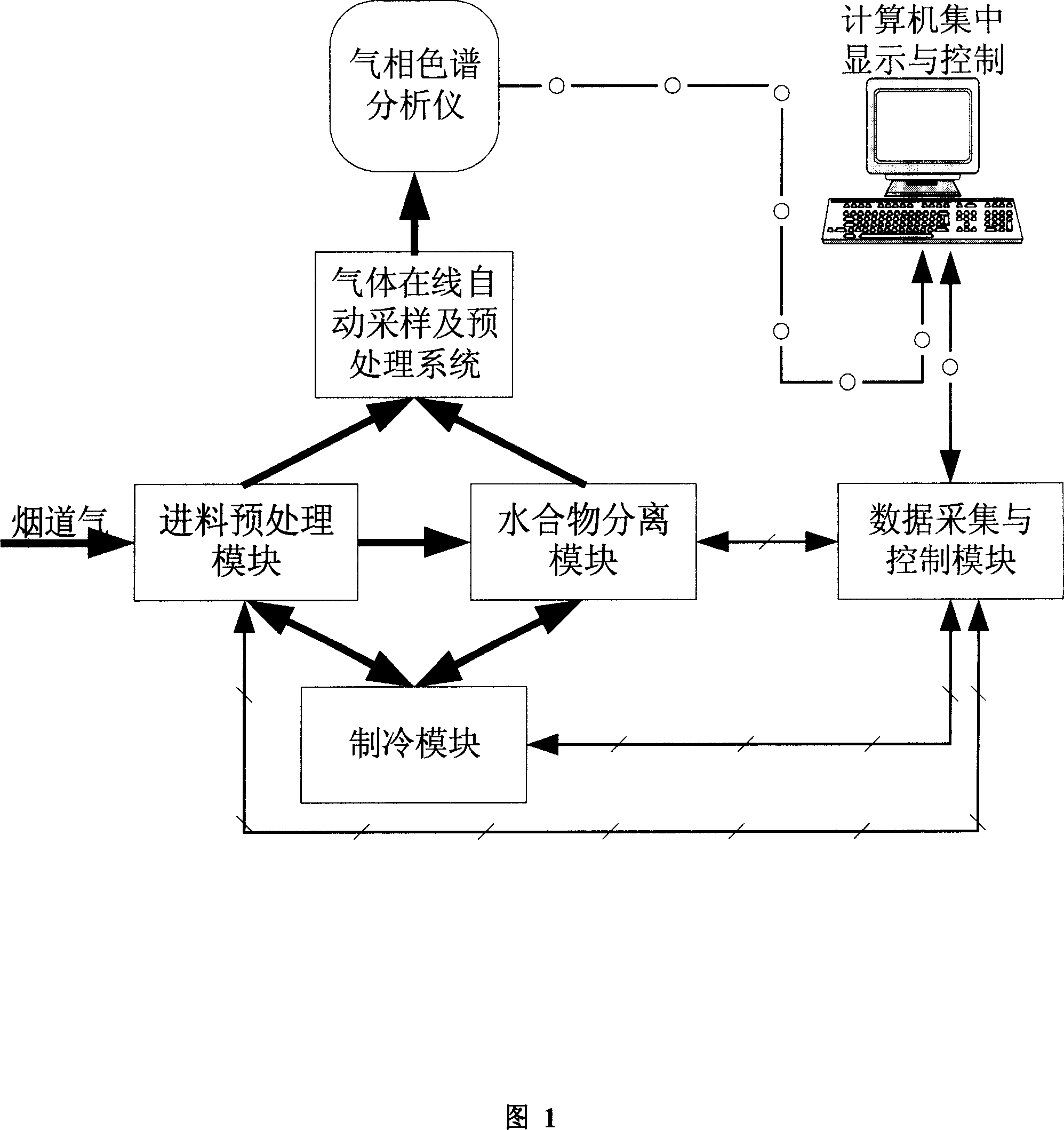
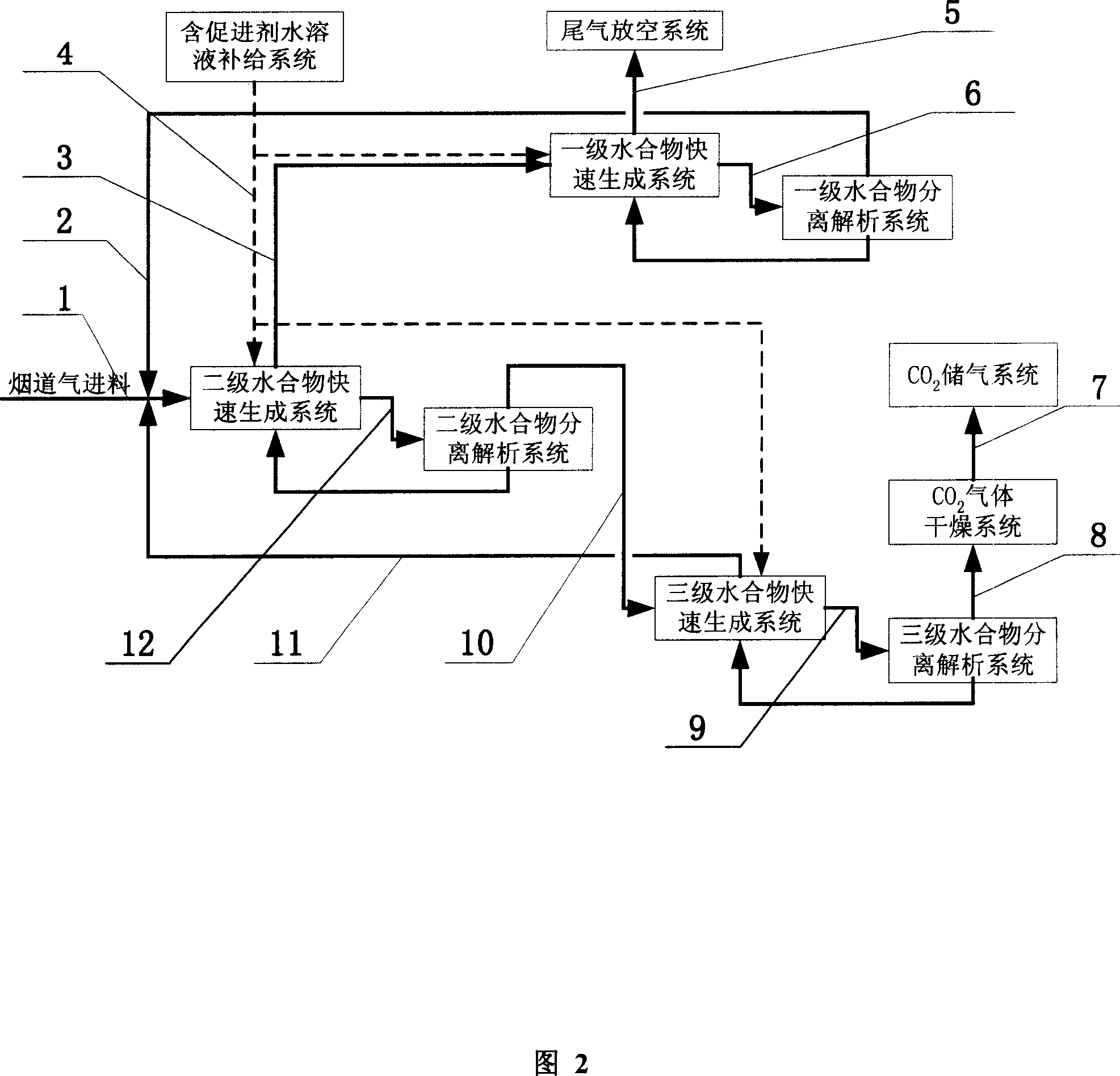
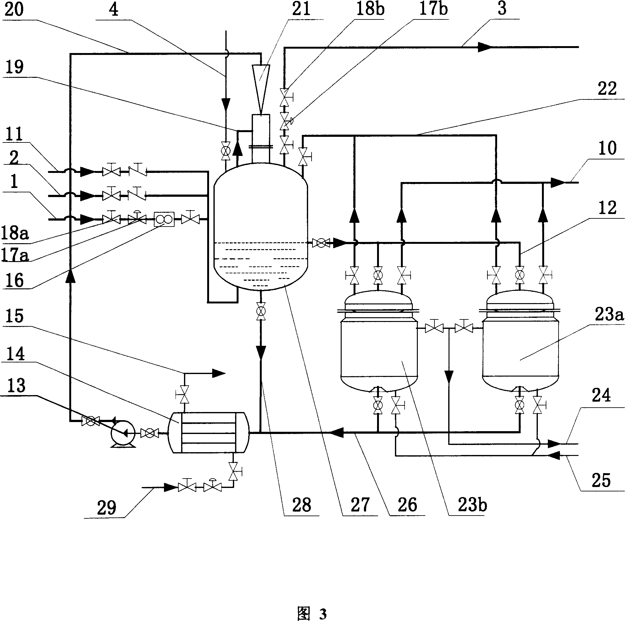
[0059] As shown in Figures 1, 2, and 3, after the flue gas is pretreated by water washing, drying, compression, and pre-cooling, the CO in the flue gas 2The molar concentration is about 18%, the pressure is about 2.0MPa, and the temperature is 4°C. The pretreated flue gas enters the secondary hydrate synthesis through the flue gas feed pipe 1, the feed regulating valve 18a, and the flow meter 16. Kettle 27; aqueous solution containing 1.0% accelerator sodium lauryl sulfate is added to primary, secondary, and tertiary hydrate synthesis kettles through aqueous solution supply system and aqueous solution supply pipeline 4; The aqueous agent solution is cooled to 2°C through the liquid phase circulation pipe 28 of the secondary hydrate synthesis tank to the heat exchanger 14, and then enters the microbubble jet full-mix reactor 21 through the circulation pump 13 and the liquid inlet pipe 20 of the microbubble jet full-mix reactor The flue gas in the gas-phase region at the top of ...


PUM


Abstract

The present invention proposes hydrate process and apparatus for separating gas mixture continuously. The countercurrent continuous separation process in three serially connected stages is adopted to raise the CO2 recovering rate from fume, the CO2 concentration in the product and the separation rate and efficiency. Each of the separating systems consists of a hydrate synthesizer, a hydrate decomposer, a circulating pump, a heat exchanger, and a micro bubble mixing and jetting reactor. The present invention is suitable for continuous separation and enrichment of CO2 in the fume of coal burning power plant, and may be also used in the continuous separation and enrichment of gas mixture containing CO2 in chemical industry, metallurgy, petroleum and other fields.

Description

technical field [0001] The invention relates to a continuous separation technology of mixed gas, in particular to a continuous separation technology of mixed gas by hydrate method. technical background [0002] The reality of global warming is constantly sounding the alarm to people all over the world, and greenhouse effect gases, especially CO 2 Gas emissions have become one of the hottest issues in the world. As of the end of 2004, a total of 141 countries and regions around the world have approved to reduce CO emissions 2 The purpose of the "Kyoto Protocol", which came into effect on February 16, 2005, requires all countries to control the emission of greenhouse gases. Atmospheric CO 2 The main source of the continuous increase in concentration is the exhaust gas emitted from large-scale energy production in industry. my country is a country where coal is the main energy source, and this energy structure will not change for a long time in the future. Most of my count...

Claims


Application Information

Patent Timeline
Patent Type & Authority Applications(China)
IPC IPC(8): B01D53/14B01D53/62C01B31/20C01B32/50
CPCY02P20/151
Inventor 李小森陈朝阳李刚颜克凤
Owner GUANGZHOU INST OF ENERGY CONVERSION - CHINESE ACAD OF SCI
Learn More