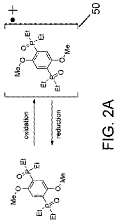
High voltage redox shuttles, method for making high voltage redox shuttles
a high-voltage redox and shuttle technology, applied in the direction of electrochemical generators, secondary cell servicing/maintenance, group 5/15 element organic compounds, etc., can solve the problems of long battery life, damage to battery components (e.g., the positive electrode or the cathode), and other problems, to achieve the effect of preventing overcharg
- Summary
- Abstract
- Description
- Claims
- Application Information
AI Technical Summary
Benefits of technology
Problems solved by technology
Method used
Image

Examples
example 1
[0050]The following example is an exemplary embodiment of the invented method and resulting product.
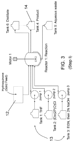
Step I
Synthesis Detail
[0051]A glass reactor (20 L, jacketed, e.g., Chemglass) equipped with drain valve, internal temperature probe, reflux condenser, gas inlet / outlet adapters and powder port was flushed with argon. The jacket of the reactor was connected to a Huber heating / chilling circulator. An argon flow was continued to inert the reactor. The reactor was charged with hydroquinone (265 g), THF (4 L) and diethyl chloro-phosphate (995 g). The process temperature was set to 18° C. Triethylamine (1 L) was added via peristaltic pump at 10 mL / min. A light blue suspension formed within 20 minutes. The reaction was stirred overnight and cooled to about −2° C. MTBE (2 L) was added. The reaction was quenched by the addition of 2 L of 2M NaOH. The layers were separated and the organic layer washed with additional 2M NaOH (2×2 L). The organic layer was then rotovaped to a purple oil. The oil...
example 2
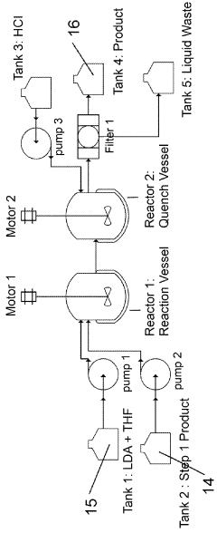
[0064]A 250 mL 3 neck flask was charged with tetraethyl (2,5-dimethoxy-1,4-phenylene)bis(phosphonate) (25.46 g, lot TD50129). A thermocouple and reflux condenser were attached. The flask was purged with inert gase (e.g., nitrogen) and the outlet gasses send to a NaOH(aq) trap. The solids were dissolved in thionyl chloride (75 mL) and the solution was heated to 65° C. with stirring. N,N-Dimethylformamide (19 mL, 4 equiv) was added via syringe pump over 1 hour. The solution was kept at temperature for 14 hours. The mixture was then cooled to room temperature.
[0065]The solids that precipitated from the reaction mixture were filtered under nitrogen and washed with toluene (2×20 mL) and MTBE (20 mL) and dried under a nitrogen stream for a time sufficient to yield substantially moisture free precipitate. (e.g., a drying protocol involves drying for about one hour to give an off-white powder. This material was split into two reactions.
[0066]The crude intermediate was slurried in 2-methylte...
example 3
[0068]A 250 mL 3 neck flask was charged with tetraethyl (2,5-dimethoxy-1,4-phenylene)bis(phosphonate) (10.0030 g, lot TD50127). A thermocouple and reflux condenser were attached. The flask was purged with an inert gas and the outlet gasses send to a NaOH(aq) trap. The solids were dissolved in thionyl chloride (25 mL) and the solution was heated to 65° C. with stirring. N,N-Dimethylformamide (7.5 mL, 4 equiv) was added via syringe pump over 1 hour. The solution was kept at temperature for 14 hours. HPLC showed some starting material. Additional DMF and SOCl2 were added. The mixture was then cooled to room temperature.
[0069]The solids that precipitated from the reaction mixture were filtered under nitrogen and washed with MTBE (2×20 mL) and dried under a nitrogen stream for 1 hour to give an off-white powder (10.3 g, theoretical 9.1 g).
[0070]The crude intermediate was slurried in 2-methyltetrahydrofuran (50 mL). The mixture was cooled to between about 0 and about −10° C. Phenylmagnesi...
PUM
| Property | Measurement | Unit |
|---|---|---|
| temperature | aaaaa | aaaaa |
| temperature | aaaaa | aaaaa |
| temperature | aaaaa | aaaaa |
Abstract
Description
Claims
Application Information