
Materials with extremely durable intercalation of lithium and manufacturing methods thereof

a technology of lithium and intercalation, which is applied in the direction of batteries, ceramics, cell components, etc., can solve the problems of low power performance and limited capacity of graphitic anodes, insufficient current lead acid automobile batteries for next-generation all-electric and hybrid electric vehicles, and fundamentally limited materials, etc., to achieve convenient scalable, improve process, and reduce the effect of cos

Active Publication Date: 2018-12-04
GRP 14 TECH INC
View PDF336 Cites 63 Cited by
  • Summary
  • Abstract
  • Description
  • Claims
  • Application Information

AI Technical Summary

Benefits of technology

[0043]In more embodiments is provided a composite comprising a porous carbon scaffold and silicon, wherein the composite comprises from 35 to 65% silicon by weight, and wherein, the porous carbon scaffold has a pore structure comprising less than 20% micropores, greater than 60% mesopores, less than 30% macropores and a total pore volume between 0.1 and 0.5 cm3 / g, as determined by nitrogen sorption.
[0044]Accordingly, the present disclosure provides both novel compositions of matter in addition to manufacturing methods thereof, wherein said materials exhibit remarkably durable intercalation of lithium when incorporated into an electrode of a lithium based energy storage device. In some embodiments, the lithium based electrical energy storage device is a lithium ion battery or lithium ion capacitor.
[0045]These and other aspects of the invention will be apparent upon reference to the following detailed description. To this end, various references are set forth herein which describe in more detail certain background information, procedures, compounds and / or compositions, and are each hereby incorporated by reference in their entirety.

Problems solved by technology

For example, current lead acid automobile batteries are not adequate for next generation all-electric and hybrid electric vehicles due to irreversible, stable sulfate formations during discharge.
Traditional lithium ion batteries are comprised of a graphitic carbon anode and a metal oxide cathode; however such graphitic anodes typically suffer from low power performance and limited capacity.
However, these materials are fundamentally limited by the substantial swelling that occurs when they are fully intercalated with lithium.
This swelling and shrinkage when the lithium is removed results in an electrode that has limited cycle life and low power.
The solution thus far has been to use very small amounts of alloying electrochemical modifier in a largely carbon electrode, but this approach does not impart the desired increase in lithium capacity.
However none of these processes has proven to combine a scalable process that results in the desired properties.
Over many cycles, the capacity of said materials is susceptible to fading.
SEI formation on the negative electrode is an irreversible reaction that consumes cyclable Li-ions from the positive electrode leading to most of the capacity loss observed in the first lithiation / delithiation cycle of secondary lithium-ion batteries.
The repeated expansion and contraction of silicon-based anode materials leads to instability of SEI, for example, cracking and reformation, concomitantly contributing to the capacity fade of the anode.
The extreme surface volume expansion will cause the silicon particle to tear apart away from the inside, cracking and fracturing.
Once silicon has pulverized the cell will fail, as there is no known method to salvage the performance.
Current technologies for achieving nano sized silicons are expensive and difficult to scale.
In another example, a process utilized SiCl4 reduction at room temperature under an inert atmosphere, however the product obtained at room temperature was not fully crystallized, requiring further high temperature annealing.
Furthermore, these approaches are not suitable for enabling commercial utility; the scalability and material yields are insufficient to allow for their use in anode production for lithium secondary batteries.

Method used


Image

  • Materials with extremely durable intercalation of lithium and manufacturing methods thereof
  • Materials with extremely durable intercalation of lithium and manufacturing methods thereof
  • Materials with extremely durable intercalation of lithium and manufacturing methods thereof

Examples


example 1

Performance Model of Novel Composite Materials

[0407]A full cell model was developed to simulate the approximate size and energy of an 18650-type cell. LCO was chosen as the default cathode. The model accounts for material properties (density, packing, volume expansion), electrochemical performance characteristics (operating voltage, capacity, irreversible capacity), and cell level changes (required electrolyte, void volume). Table 2 compares the cell level properties from a commercially available cell and the output from the model. Similar values are calculated using the model, providing confidence in the model's ability to represent system level changes.

[0408]

TABLE 2Validation of performance model for a commercial cell.Standard CommercialComponentCellModel PredictionCell typeStacked Pouch CellStacked Pouch CellAnodeUnknownGraphiteCathodeUnknownLCOCell capacity3.28 Ah3.55 Ah (calculated)Operating Voltage3.7 V3.7 V (calculated)Cell energy199 Wh / kg174 Wh / kg435 Wh / L(calculated)437 Wh / L...

example 2

Examples of Porous Carbon Scaffold Materials

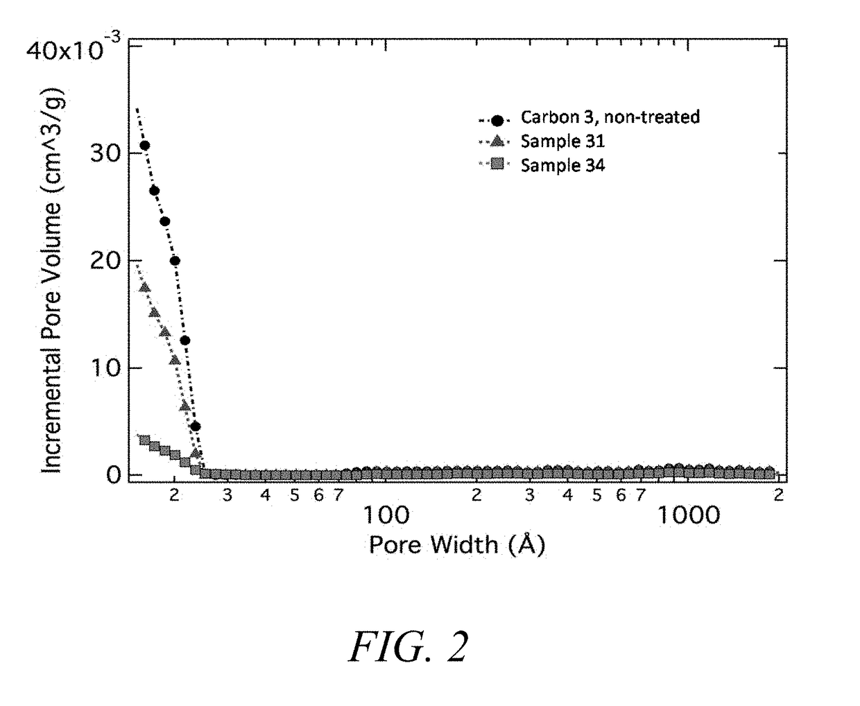
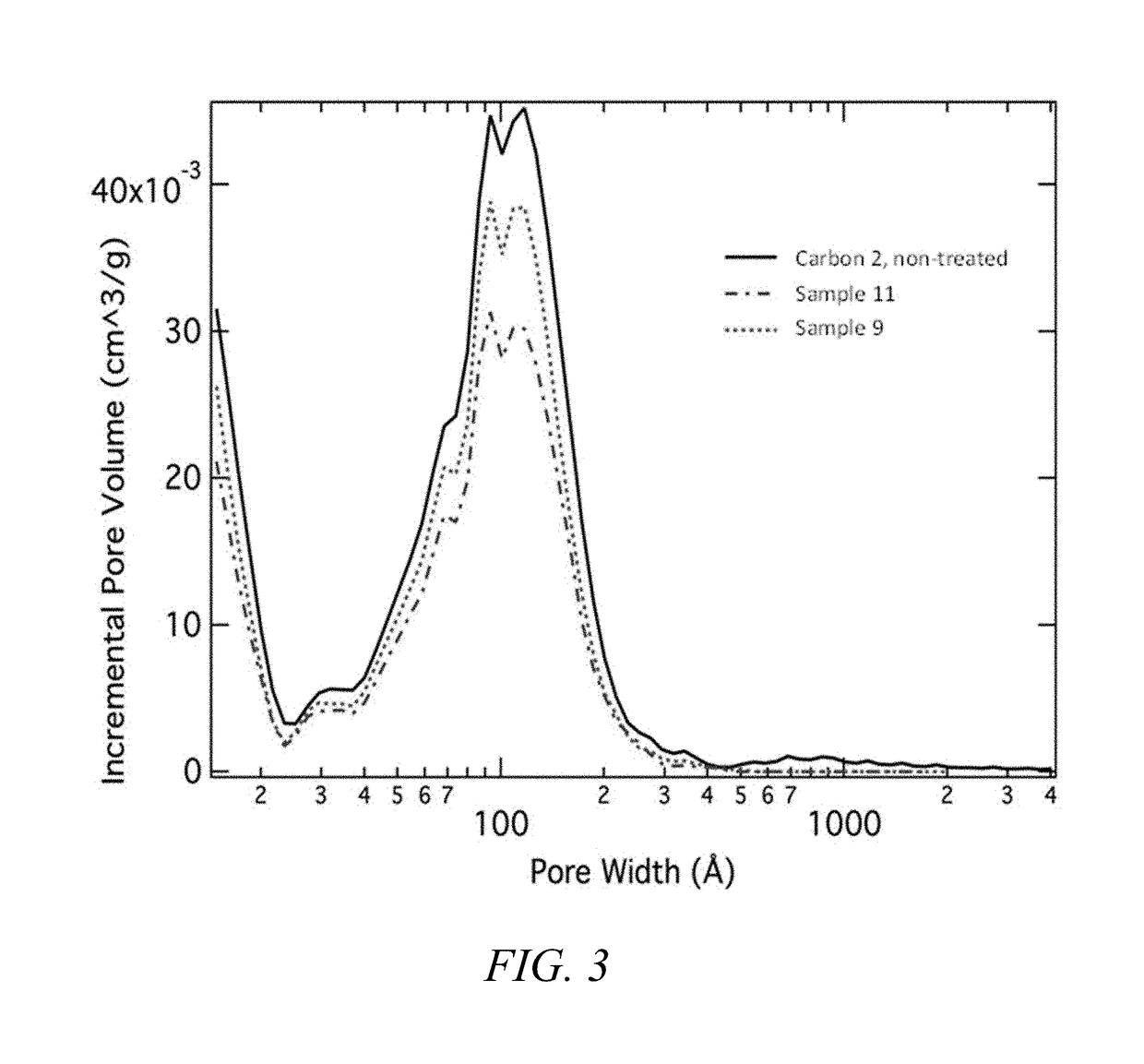
[0411]The variety of various porous carbon scaffold materials were obtained for study. A listing of the physicochemical attributes of the carbon is listed in Table 4.

[0412]Carbon 1 was a commercial carbon; in addition to the characteristics reported in Table 2, the Dv,100 was 11.62 microns, the Dv,10 was 0.6 micron, tap density was 0.27 g / cm3, the pH was 5.3, the ash content was 0.016%, and the sum all impurities detected by PIXE was as follows: silicon=48.680 ppm, calcium=12.910 ppm, iron=22.830 ppm, nickel=3.604 ppm, chromium=5.521.

[0413]Carbon 2 was a commercial carbon; in addition to the characteristics reported in Table 1, the Dv,100 was 18.662 microns, the Dv,10 was 1.2 micron, the span for particle size was 1.194, the uniformity for particle size distribution was 0.367, the tap density was 0.2347 g / cm3, the pH was 6.709, the ash content was 0.005%, and the sum all impurities detected by PIXE was as follows: calcium=20.5 ppm, iron=4....

example 3

Production of Various Composite Materials Via Silicon Deposition on Porous Silicon Scaffold

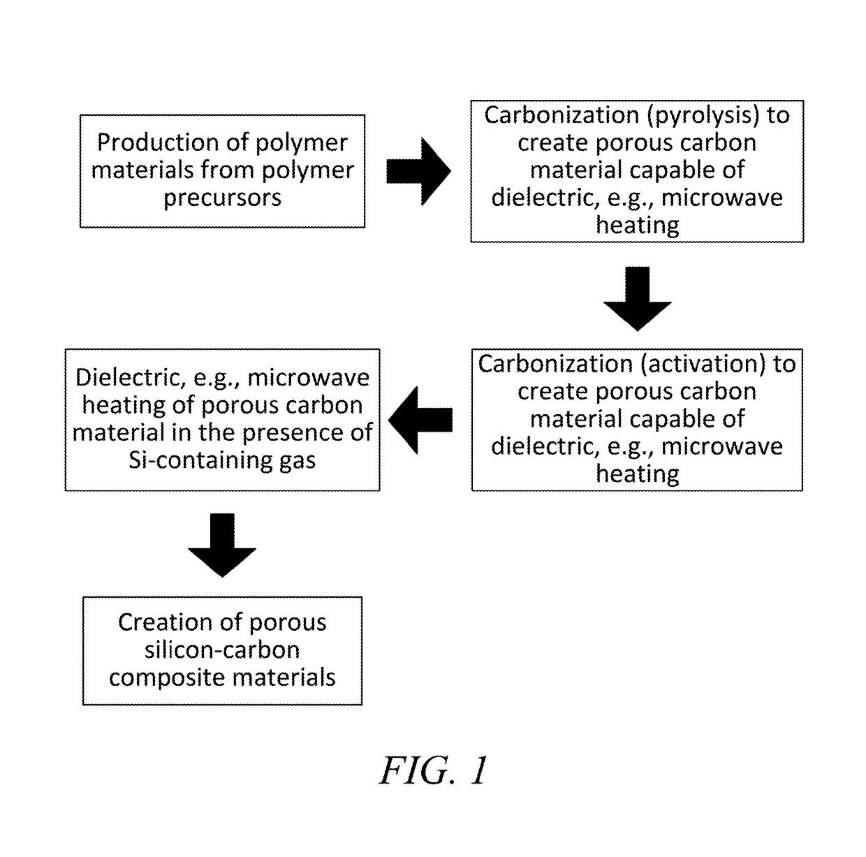
[0426]A variety of different composite materials were produced according to current disclosure, in this example, the silicon was embedded within a porous carbon scaffold via a chemical vapor deposition technique employing silane gas, as generally described herein. For this specific example, samples were processed in a tube furnace with 2 mol % silane gas flow mixed with nitrogen gas, and held for various times and temperatures as noted. A summary of sample processing is presented in Table 5. The final loading of silicon in the silicon carbon composite can be determined as known in the art, for example from the weight loss observed employing thermal gravimetric analysis (TGA), a technique known in the art.

[0427]

TABLE 5Summary of composite samples produced according to Example 3.CompositePorousSet Temp.Flow ratePressureSilane dwellTotal wtwt % siliconSample #Carbon(° C.)(sccm)(Torr)time (min)% g...


PUM

PropertyMeasurementUnit
skeletal densityaaaaaaaaaa

Abstract

Composites of silicon and various porous scaffold materials, such as carbon material comprising micro-, meso- and / or macropores, and methods for manufacturing the same are provided. The compositions find utility in various applications, including electrical energy storage electrodes and devices comprising the same.

Description

STATEMENT OF GOVERNMENT INTEREST[0001]This invention was made in part with government support under Award No. DE-EE0007312 awarded by the Department of Energy, Office of Energy Efficiency & Renewable Energy. The United States Government has certain rights in this invention.BACKGROUND[0002]Technical Field[0003]The present invention generally relates to novel materials exhibiting extremely durable intercalation of lithium, methods for their manufacturing, and methods of their use, for example for energy storage applications. The novel materials comprise a porous scaffold, for example a carbon exhibiting a pore volume comprising micropores, mesopores, and / or macropores, wherein said volume is impregnated with silicon, in some embodiments, the impregnated silicon is nano-sized and / or nano-featured. The silicon-impregnated porous scaffold can be further coated to reduce any remaining surface area, for example, coated with carbon or conductive polymer. Such silicon-impregnated carbon mate...

Claims


Application Information

Patent Timeline
Patent Type & Authority Patents(United States)
IPC IPC(8): H01M4/587C04B35/524C04B38/00C04B41/00H01M4/04H01M4/38H01M4/134H01M4/36H01M4/133C04B41/50H01M10/0525H01M4/62C04B41/85H01M4/02C04B111/00
CPCH01M4/587C04B35/524C04B38/0051C04B38/0064C04B41/009C04B41/5096C04B41/85H01M4/0416H01M4/133H01M4/134H01M4/362H01M4/364H01M4/366H01M4/386H01M4/625H01M10/0525C04B35/522C04B38/0054C04B41/4529H01M2220/20H01M2004/021C04B2235/6581C04B2235/616C04B2111/00853C04B2235/428H01M10/052C01B32/05C01B33/021H01M2004/027Y02E60/10H01B1/04
Inventor SAKSHAUG, AVERYCOSTANTINO, HENRY R.FEAVER, AARON M.THOMPKINS, LEAH A.GERAMITA, KATHARINEKRON, BENJAMIN E.FREDRICK, SARAHAFKHAMI, FARSHIDSTRONG, ADAM
Owner GRP 14 TECH INC
Learn More