Heated airlock feeder unit

a feeder unit and airlock technology, applied in the direction of supercritical condition processes, charging devices, products, etc., can solve the problems of not allowing molten materials, devices that cannot tolerate heat, and hot plastics that cannot tolerate molten materials, etc., to achieve less power consumption, high power consumption, and faster processing time

Active Publication Date: 2019-03-19
GOLDEN RENEWABLE ENERGY LLC
View PDF95 Cites 9 Cited by
  • Summary
  • Abstract
  • Description
  • Claims
  • Application Information

AI Technical Summary

Benefits of technology

[0007]Existing gear boxes, designed as short as possible to reduce material and labor on fabrication, have limited function with this utility patent application, as the short gear boxes are limited on taking a cantilever load as the force of trying to hold a long heave shaft puts extreme pressure on the leading bearing resulting is reduction of the life of the bearing or requiring a heavy duty bearing to handle the force. If a heavy duty bearing is used, this results in a larger bearing creating large pockets in the gear box housing. The larger pocket reduces the ability of the housing to support the bearing, so in turn the housing will be made thicker. This increases the cost of a standard gear box. This design extends the space between the bearings and reduces load on the bearings. By spacing the bearings further apart, the cantilever load is reduced, the bearing size can be smaller and the housing can be thinner, reducing the overall cost and improving the performance. The further apart the points on connection on the bearings, the straighter the alignment on the shafts, reducing wear and increasing the life of the gear box;
[0008]A flat bar attached between the cart and the frame that allows for the apparatus to expand and contract due to heat transfer as this apparatus incorporates thinner material in the reactor allowing for better heat transfer;
[0010]The use of vapor gas (natural gas or syn-gas) and clamshell burners allowing for the external heat to be allowed in the processing of the plastic material whereas prior art used electric heater bands and internal pressure, resulting in high power consumption, to produce the heat required to process the plastic material. The use of vapor gas and clamshell burners allows for less power consumption, faster processing time, and more accurate and consistent heat production.
[0011]The use of clamshell burners allows heat to be generated over the entire exterior surface of the penetrating pipe and allowing for access to the reactor tube. The use of the clamshell burners allows for a low profile to the interior reactor reducing the amount of space between the heat source and the penetrating pipe surface, increasing the heat transfer without increasing the BTU value required by a burner system. The clamshell design combines both convection heat and radiant heat producing an even heat source around the penetrating pipe. The combining of the two types of heat is accomplished with the use of a perforated screen running the entire length of the penetrating tube and one third of the way up on the bottom inside of the clamshell burners. This design also prevents hotspots that normally occur in burner boxes. Another difference in this system compared to existing systems is that the igniting source is inside the clamshell burner box next to the perforated screen. The system contains flame sensors as well as a fan pressure switch to ensure airflow. Dual gas streams are used by adjusting the gas quantity or the air quantity, whereas existing systems use complicated air control dampers to adjust the air and gas ratio, that may cause uneven burning of the fuel creating irregular flame size. The clamshell design that is part of the Heated Airlock Feeder is not lined with refractory on all surfaces, but only on the top half of the clamshell. The fact that the lower half of the clamshell is not lined with refractory allows any heat build-up to dissipate through the entire box surface. This design also reduces the chance of auto-ignition of the mixed gas.

Problems solved by technology

There are four limitations with this design.
The first is that it will not tolerate heat as it will expand and allow the pressures to leak.
The forth is that this device will not allow for a molten material like hot plastic.
This is a limitation as atmospheric gases may not be allowed in some processes as they will cause problems downstream.
A second limitation with this device is that it will not allow for a molten material like hot plastic.
Limitations with this apparatus are that it does not create an airlock so it does not allow for the continuous feeding of plastic material and it requires a thick long barrel that requires very high horsepower to achieve the internal pressure and heat necessary to melt the plastic, translating into a high power requirement.
Applying heat above 350 degrees Celsius will cause the shredded plastic material to melt and vaporize.
It has been discovered that the prior art did not allow for the continuous feeding of heated plastic into the feeder while maintaining an air lock.
Existing gear boxes, designed as short as possible to reduce material and labor on fabrication, have limited function with this utility patent application, as the short gear boxes are limited on taking a cantilever load as the force of trying to hold a long heave shaft puts extreme pressure on the leading bearing resulting is reduction of the life of the bearing or requiring a heavy duty bearing to handle the force.
If a heavy duty bearing is used, this results in a larger bearing creating large pockets in the gear box housing.
This increases the cost of a standard gear box.
The use of vapor gas (natural gas or syn-gas) and clamshell burners allowing for the external heat to be allowed in the processing of the plastic material whereas prior art used electric heater bands and internal pressure, resulting in high power consumption, to produce the heat required to process the plastic material.
Dual gas streams are used by adjusting the gas quantity or the air quantity, whereas existing systems use complicated air control dampers to adjust the air and gas ratio, that may cause uneven burning of the fuel creating irregular flame size.
This design also reduces the chance of auto-ignition of the mixed gas.

Method used


Image

  • Heated airlock feeder unit
  • Heated airlock feeder unit
  • Heated airlock feeder unit

Examples


Embodiment Construction

[0020]While the invention will be described and disclosed herein connection with certain preferred embodiments, the description is not intended to limit the invention to the specific embodiments shown and described here, but rather the invention is intended to cover all alternative embodiments and modifications that fall within the spirit and scope of the invention as defined by claims included herein as well as any equivalents of the disclosed and claimed invention.

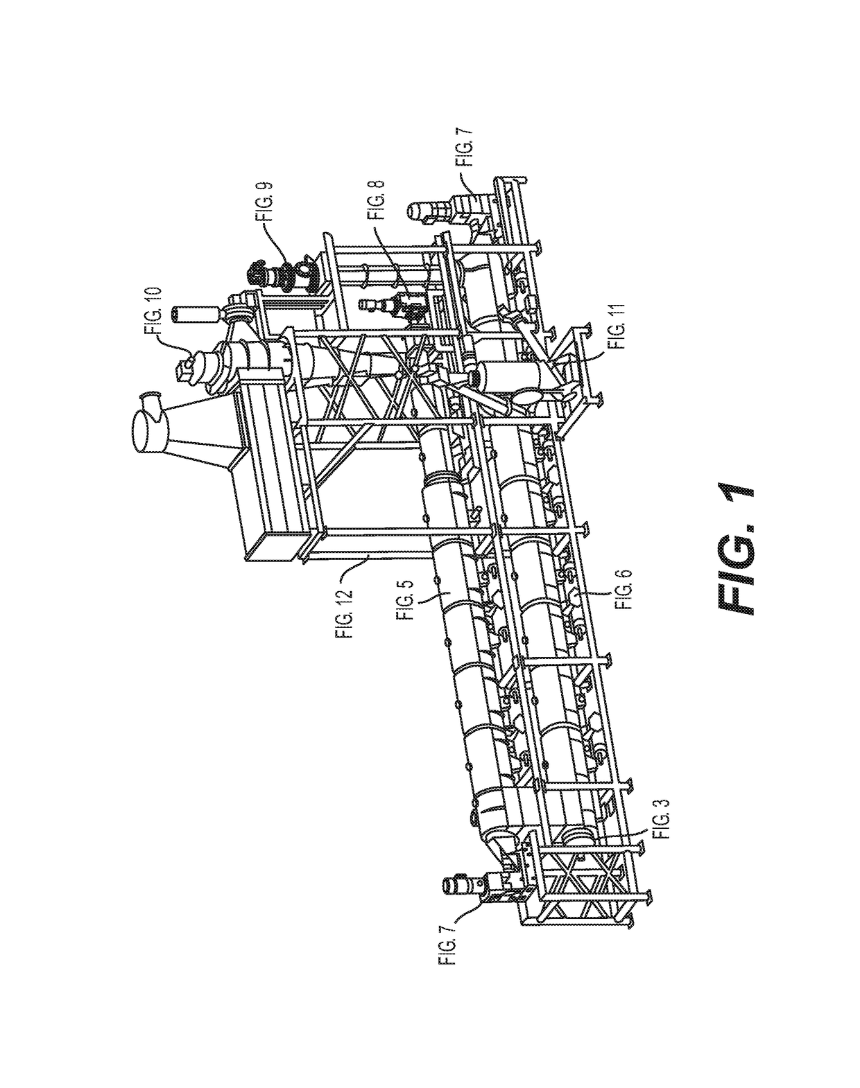
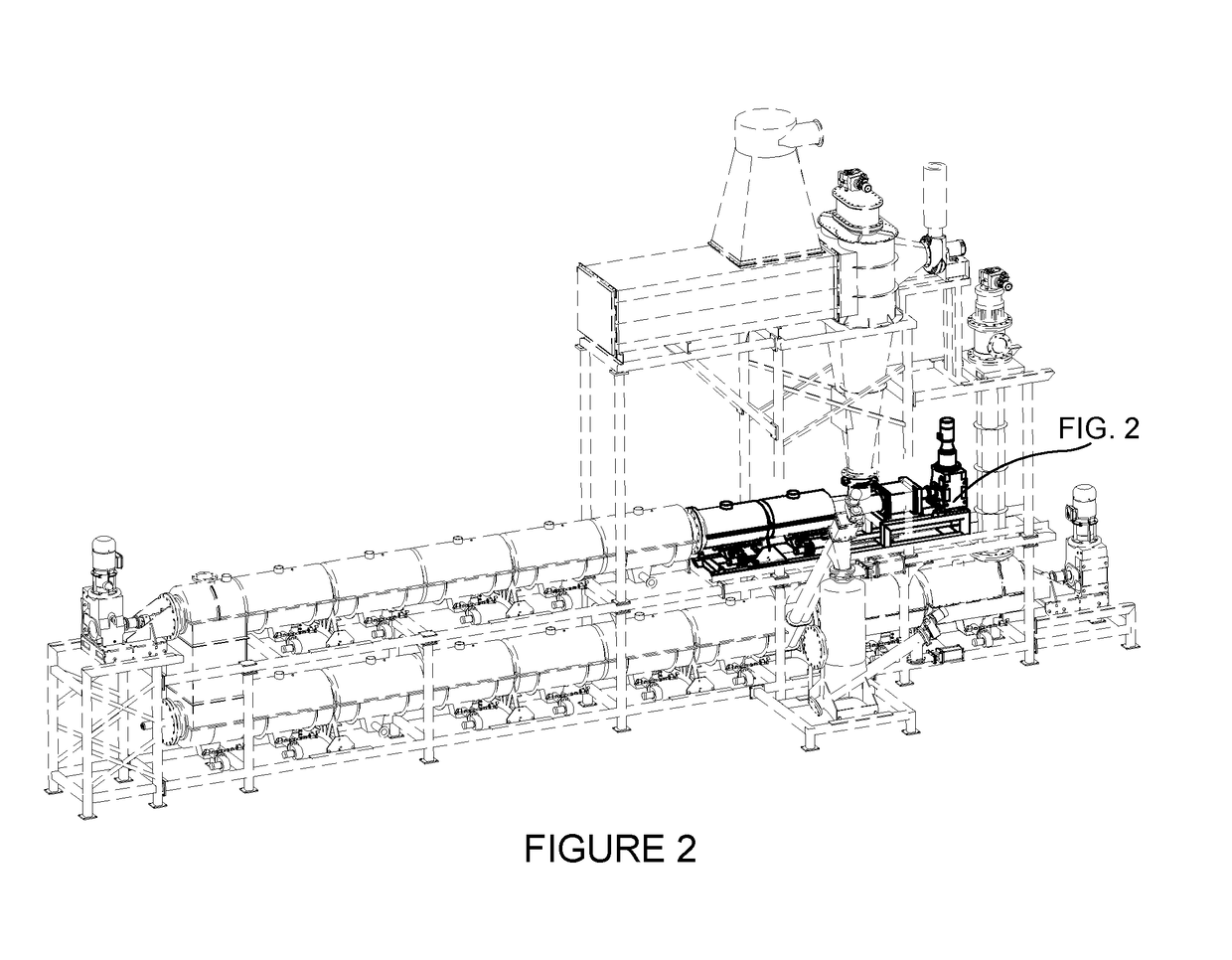
[0021]The utility patent this application describes allows the application of back pressure to the feed material between the cold material and the heated, melting material (molten plastic). The main components of the Heated Airlock Feeder system are the drive, coupling, gearbox, augers, housing, clamshell burner boxes, expansion cart, and support frame. FIG. 1 depicts the entire assembly of the re-usable energy reactor system. FIG. 2 depicts the Heated Airlock Feeder that is part of the entire assembly of the re-useable ...


PUM

PropertyMeasurementUnit
lengthaaaaaaaaaa
pressureaaaaaaaaaa
diameteraaaaaaaaaa

Abstract

A Heated Airlock Feeder is disclosed. The Heated Airlock Feeder allows for the continuous feeding of solid, shredded plastic into a reactor tube surrounded by clamshell burner boxes. Inside of the reactor tube, two augers, one with right hand flights and one with left hand flights are welded to smooth augers to create two continuous augers that push solid plastic material, liquid plastic material and molten plastic material through two small holes. As the plastic is in its molten state while being forced through the two small holes, an airlock is formed preventing air form entering the system. As the solid, shredded plastic is fed into the system, an airlock is formed allowing for the continuous feeding of the system. The clamshell burner boxes allow for convection and radiant heat allowing for even, continuous heat.

Description

REFERENCE TO RELATED APPLICATIONS[0001]This application discloses material that is related to material disclosed in a provisional application filed on Dec. 9, 2014, and having Ser. No. 62 / 089,617, titled “Feeding Reactor / Extruder”, incorporated herein in its entirety by reference.BACKGROUND OF THE INVENTION(a) Field of the Invention[0002]The present invention improves on extruder technology as it allows for the continuous feeding of the reactor while using much less power, thus increasing efficiency and lowering the cost of production for the fuel product. This application relates to an apparatus that is part of a re-useable fuel processing unit. This apparatus allows for the continuous feeding of plastic into the unit since the apparatus described herein creates a process by which heat is tolerated in an anaerobic environment, atmospheric pressure does not leak in and out of the apparatus, air does not leak into the apparatus, and plastic in solid and heated liquid form does not ca...

Claims


Application Information

Patent Timeline
Patent Type & Authority Patents(United States)
IPC IPC(8): C10B47/44C10B23/00C10B31/08C10B53/07C10B13/00
CPCC10B47/44C10B23/00C10B53/07C10B31/08C10B13/00B01J3/008C10G1/065Y02P20/143C10G2300/30C10G2300/4006C10G2300/4012C10G1/10C10G2300/1003
Inventor OLUWASEUN, OLUWADARETENORE, ANTHONY F.FOWLER, DAVID
Owner GOLDEN RENEWABLE ENERGY LLC
Why Eureka
Try Eureka