Method for producing acetic acid

a technology of acetic acid and evaporator, which is applied in the direction of carboxylic preparation from carbon monoxide reaction, separation process, organic chemistry, etc., can solve the problem of easy precipitation of catalyst, achieve significant suppression of catalyst precipitation and accumulation in the evaporator, improve acetic acid productivity, and efficiently recycle

Active Publication Date: 2019-04-23
DAICEL CHEM IND LTD
View PDF18 Cites 0 Cited by
  • Summary
  • Abstract
  • Description
  • Claims
  • Application Information

AI Technical Summary

Benefits of technology

[0021]According to the present invention, an evaporator has a structure where an inclination angle of inside wall surface of an inverted truncated conical cylindrical connection portion which joins an upper cylindrical portion having a large diameter and a lower cylindrical portion having a small diameter in an evaporator body part is in a specific range, and / or a structure designed such that a linear velocity of a residual liquid stream passing through a gap between a vortex breaker disposed in the evaporator and the bottom surface of the evaporator is not less than a specific value. Therefore, catalyst precipitation and accumulation in the evaporator can be significantly suppressed, and catalysts can be efficiently recycled to the reaction vessel. Therefore, a catalyst concentration in the reaction vessel is kept constant. This can make a significant contribution to maintenance and improvement in acetic acid productivity and securing of safety operation.

Problems solved by technology

This carbonylation process of the methanol method has the major advantage that acetic acid can be efficiently produced from inexpensive raw materials, but presents the problem that the catalyst is easily precipitated.
Among others, the most important challenges are to prevent catalyst precipitation in an evaporator where the catalyst is most easily precipitated, and to improve the rate of catalyst recycle from the bottom of the evaporator to the reaction vessel.

Method used


Image

  • Method for producing acetic acid
  • Method for producing acetic acid

Examples


example 1

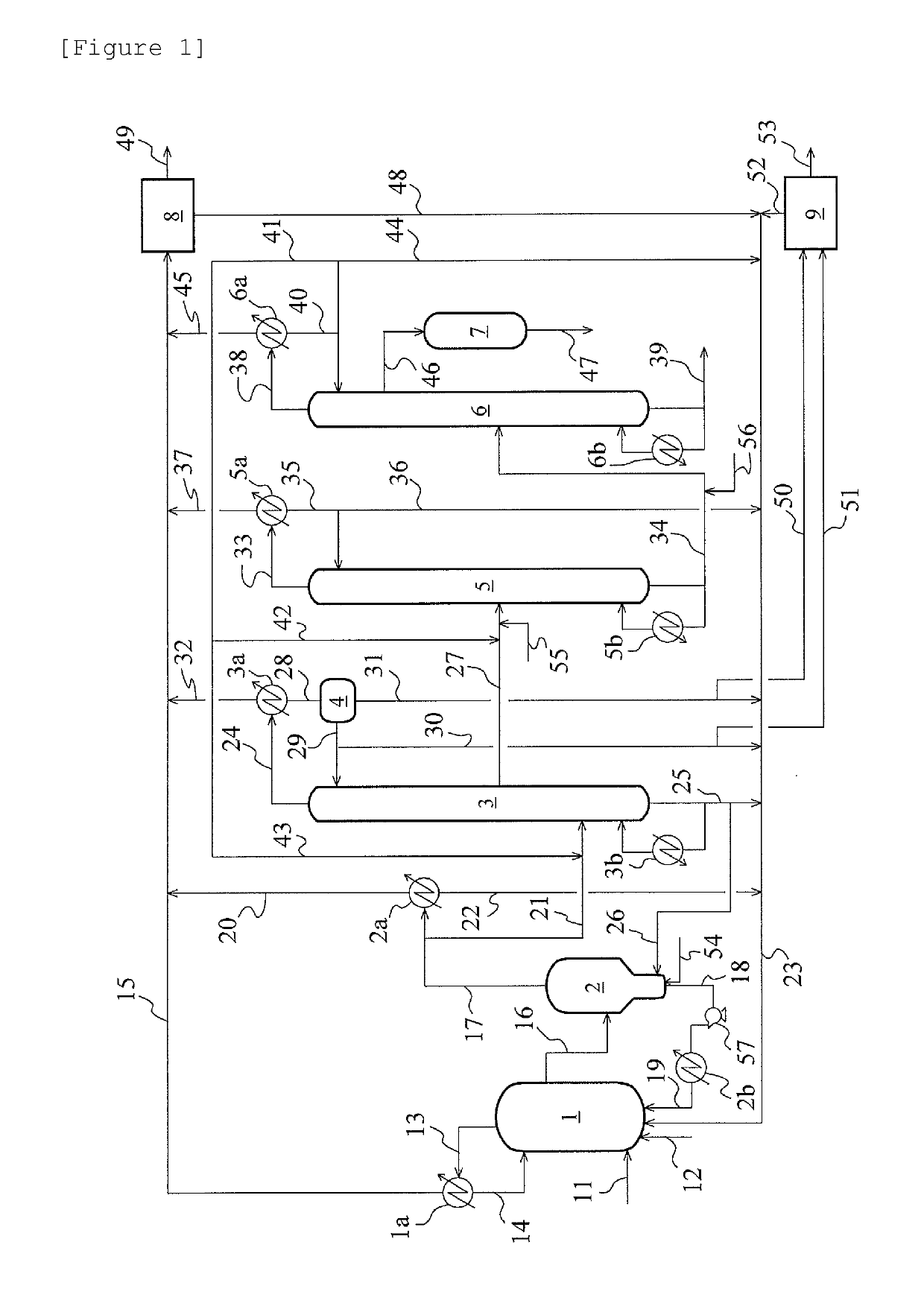
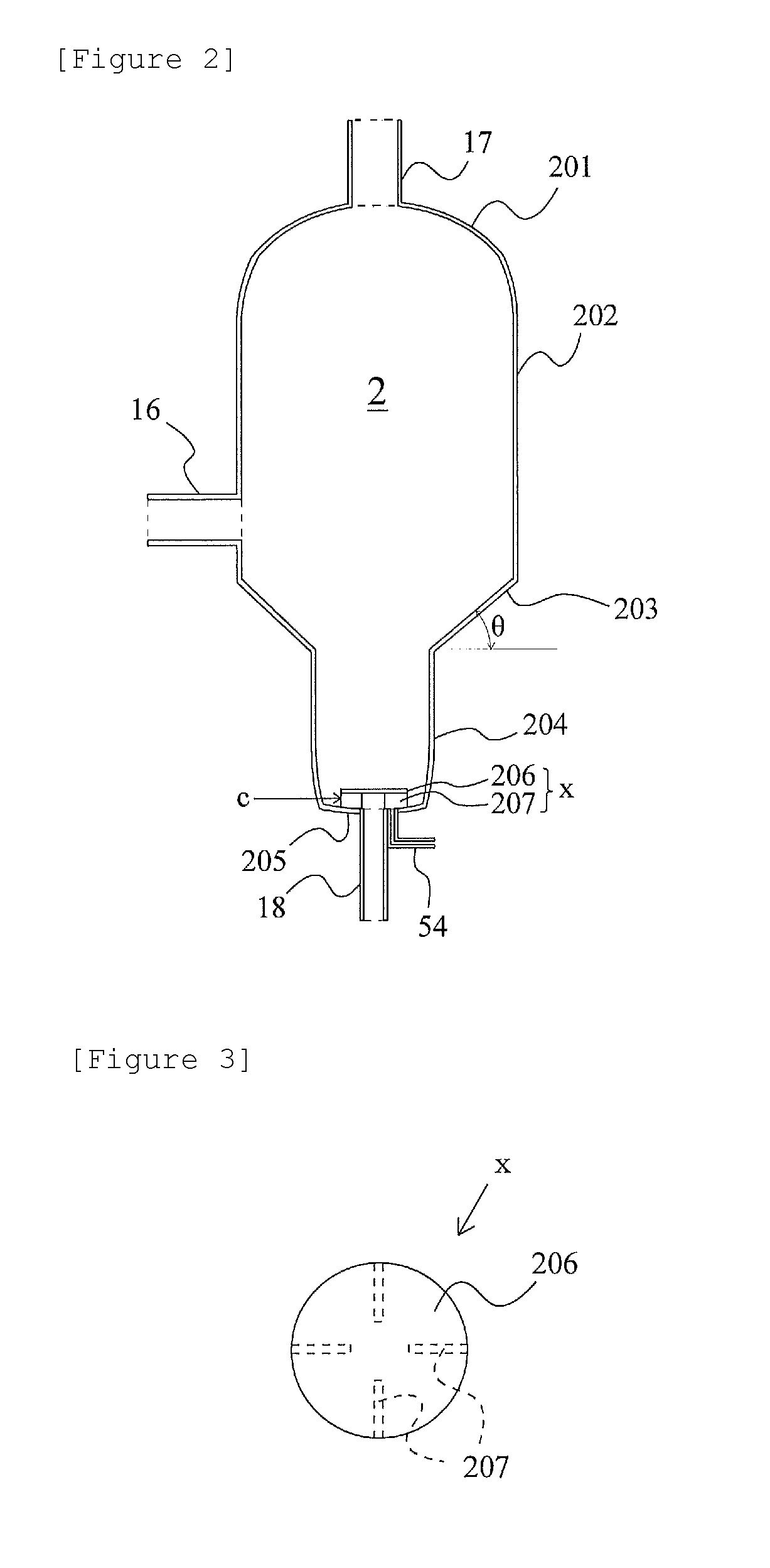
[0078]An experiment was conducted in a bench plant based on the acetic acid production flow of FIG. 1. Methyl iodide, water, methyl acetate, acetic acid, lithium iodide, and a rhodium catalyst ([Rh(CO)2I2]−) were fed to the reaction vessel 1 at a total pressure of 2.8 MPa (gauge pressure) and 187° C., and methanol and carbon monoxide [reaction vessel CO partial pressure (absolute pressure): 1.2 MPa] were continuously reacted to isolate a reaction mixture liquid (7.9% by mass of methyl iodide, 2.6% by mass of water, 2.0% by mass of methyl acetate, acetic acid (balance), 13.9% by mass of lithium iodide, and 910 ppm by mass of the rhodium catalyst). The obtained reaction mixture liquid was flashed [pressure: 0.15 MPa (gauge pressure), temperature: 143° C.] in the evaporator 2 shown in FIG. 2. A vapor (volatile component) from the evaporator 2 was fed to the distillation column 3 and distilled to obtain crude acetic acid as the side stream 27. The components other than the crude acetic ...

example 2

[0082]The same experiment as in Example 1 was conducted except that in the evaporator 2, the θ was set to 45°, and the linear velocity r was set to 10 m / h. As a result, the average Rh precipitation rate for 100 hours was 0.15 g / h. After the 100-hour experiment, the evaporator 2 and the bottom fraction line were opened, and their insides were examined. As a result, the catalyst was not attached on the inside wall surface of the connection portion 203. However, precipitated Rh was attached on the piping interior from the bottom of the evaporator bottom part 205 to the catalyst circulation pump 57.

example 3

[0083]The same experiment as in Example 1 was conducted except that in the evaporator 2, the θ was set to 60°, and the linear velocity r was set to 10 m / h. As a result, the average Rh precipitation rate for 100 hours was 0.08 g / h. After the 100-hour experiment, the evaporator 2 and the bottom fraction line were opened, and their insides were examined. As a result, only a very small amount of the catalyst was attached on the inside wall surface of the connection portion 203 and the piping interior from the bottom of the evaporator bottom part 205 to the catalyst circulation pump 57.


PUM

PropertyMeasurementUnit
inclination angleaaaaaaaaaa
linear velocityaaaaaaaaaa

Abstract

Provided is a method for producing acetic acid, which suppresses catalyst precipitation and accumulation in an evaporator, can efficiently recycle catalysts to a reaction vessel, and can contribute to maintenance and improvement in acetic acid productivity and securing of safety operation. In the method, the evaporator has a catalyst precipitation and accumulation prevention structure: (a) structure where inclination angle θ of inside wall surface of an inverted truncated conical cylindrical connection portion is 5° to 85°; and / or (b) structure where a vortex breaker comprising a plate-like vortex breaker main body and a leg is disposed such that the vortex breaker main body covers right above the connection portion of an evaporator bottom part to a residual liquid stream recycle line, and linear velocity r of the residual liquid stream passing through a gap between the vortex breaker main body and the evaporator bottom part is larger than 10 m / h.

Description

TECHNICAL FIELD[0001]The present invention relates to a method for producing acetic acid. The present application claims the priorities of Japanese Patent Application No. 2016-211922 filed in Japan on Oct. 28, 2016 and Japanese Patent Application No. 2017-039388 filed in Japan on Mar. 2, 2017, the contents of which are incorporated herein by reference in their entirety.BACKGROUND ART[0002]A carbonylation process of a methanol method is known as an industrial method for producing acetic acid. In this process, for example, methanol and carbon monoxide are reacted in the presence of a catalyst in a reaction vessel to produce acetic acid. The obtained reaction mixture is separated in an evaporator into a vapor phase containing acetic acid and lower boiling point components and a residual liquid phase containing acetic acid and the catalyst. The residual liquid phase is recycled to the reaction vessel while the vapor phase is separated by distillation into lower boiling point components ...

Claims


Application Information

Patent Timeline
Patent Type & Authority Patents(United States)
IPC IPC(8): C07C51/12B01D53/14C07C51/44B01D1/30B01D3/14
CPCC07C51/12B01D1/30B01D3/148B01D53/1418C07C51/44C07C53/08B01D53/1487B01D53/1493B01D2252/20B01D2252/2021
Inventor SHIMIZU, MASAHIKO
Owner DAICEL CHEM IND LTD
Why Eureka
Try Eureka