Systems for utilizing the water content in fluid from a renal replacement therapy process

a technology of renal replacement therapy and fluid, applied in the field of renal replacement therapy system, can solve the problems of large water consumption, large water volume, and need to replace a large amount of water, and achieve the effect of enhancing the amount and the rate of water transfer, and reducing the cost of treatmen

Active Publication Date: 2019-05-21
AQUAPORIN AS
View PDF15 Cites 6 Cited by
  • Summary
  • Abstract
  • Description
  • Claims
  • Application Information

AI Technical Summary

Benefits of technology

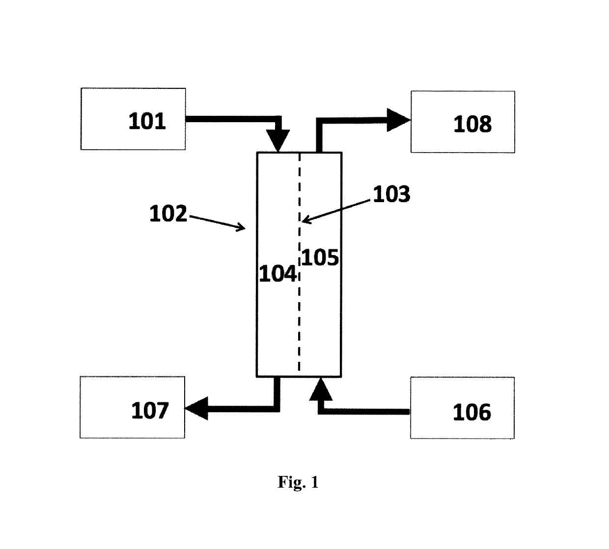
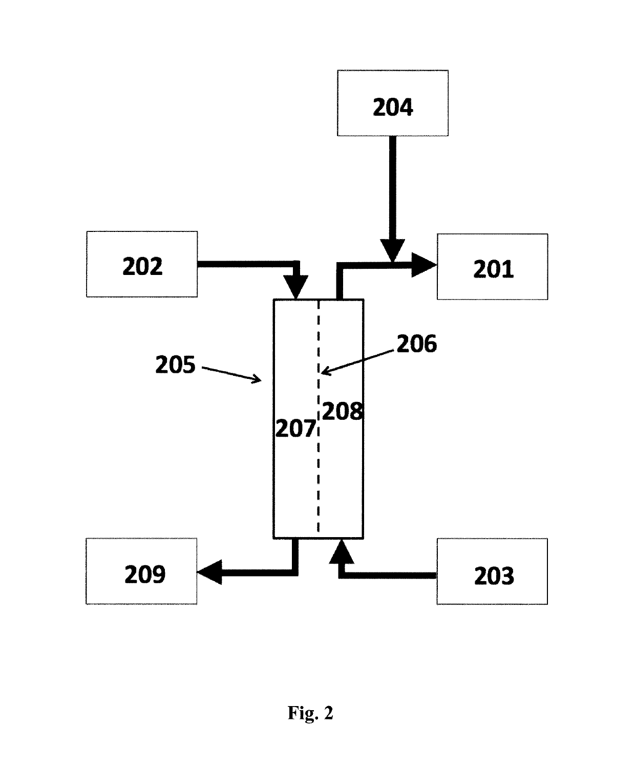
[0008]In addition, said system may comprise a forward osmosis (FO) unit (102) comprising a forward osmosis membrane (103) having a feed side (104) and a draw side (105), wherein the feed side is in fluid communication with filtrate waste fluid or spent fluid from a patient undergoing a renal replacement therapy; and wherein the draw side is in fluid communication with either a supply of dialysis concentrate, a supply of electrolyte replacement concentrate, or a flow of concentrated blood having undergone hemofiltration (106) or a combination of one or more of such sources, and where said forward osmosis membrane has an active layer which comprises nanoporous water channels such as aquaporin water channels. The FO unit may conveniently be in the form of a filter cartridge comprising a hollow fiber module. Such a module has the advantage of being compact and has a well-known form factor for use in hemofiltration apparatus. In addition, the module can be easy to replace after use in single use applications in continuos renal replacement therapies.
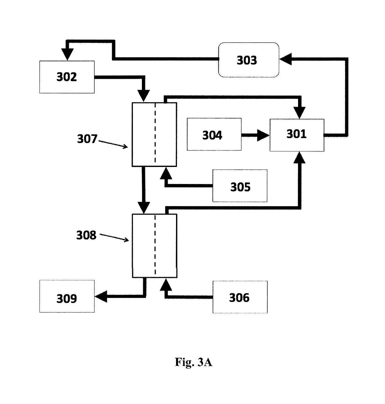
[0016]The system of the invention for utilizing the pure water content in spent fluids, such as filtrates from hemofiltration therapy, may further provide means for water extraction from filtrates and spent dialysate fluids using a draw solution, such as a stream of concentrated blood and / or fresh replacement fluid or dialysate concentrate for forward osmosis water transport across a semipermeable membrane ideally only allowing H2O transportation through nanopores, e.g. such as the water channels of aquaporin proteins. The semipermeable forward osmosis membrane useful in the system of the invention would preferably have high salt rejection and high water flux, preferably combined with a low molecular weight cut-off, MWCO. Several new membrane preparation methods for forward osmosis applications have emerged, such as preparation of thin film composite (TFC) membranes with a customized polysulfone (PSI) support, electrospun support, TFC membranes on hydrophilic support and hollow fiber membranes, cf. review by Alsvik and Hagg (2013) who describes several FO membranes having high sodium chloride rejection rates of more than about 95% and high water flux. Advantages of the system of the present invention may include: reduced energy consumption for reverse osmosis (RO) and ultrafiltration (UF) water purification and reduced water consumption in renal replacement therapy through reuse of water from hemofiltration filtrate and / or spent dialysate fluids; as well as reduction of risk of body exposure to external toxins such as organic water pollutants and endotoxins. In addition, the use of the highly selective aquaporin membranes described herein may significantly reduce or eliminate reverse flux of low molecular weight metabolites and the like from the waste fluids during (osmotic) filtration processes, thus enabling the use of said aquaporin membranes in renal assist devices and artificial kidney as well as for the re-use of pure water from said spent or waste fluids.

Problems solved by technology

This means that a considerable volume of water may have to be replaced depending on the individual patient's need.
However, it requires large scale consumption of highly purified water for the preparation of replacement fluids as well as dialysate solutions.
However, due to limitations on draw solutes such as salts and glucose, Talaat concludes that a modified dialysis therapy prescription such as a prolonged daily therapy is necessary, and he further proposes to use a multilayer FO plate and frame module to be specifically built for testing the hypotheses.

Method used


Image

  • Systems for utilizing the water content in fluid from a renal replacement therapy process
  • Systems for utilizing the water content in fluid from a renal replacement therapy process
  • Systems for utilizing the water content in fluid from a renal replacement therapy process

Examples


example 1

otentials of Dialysate Concentrates Vs Ready Dialysates

[0102]The osmotic pressure of one example of an acid and a basic (bicarbonate) concentrate and the resulting ready-to-use dialysate was calculated using OLI Analyzer Studio 9.0 (OLI Systems Inc., NJ, US). In the calculated example, 1 L of the liquid acid concentrate is to be mixed with 1.575 L of bicarbonate concentrate and 42.425 L of purified water to give 45 L of ready-to-use dialysate. Table 4 gives the compositions of the three liquids and Table 5 shows the calculated osmotic pressures.

[0103]

TABLE 4Compositions of the liquidsCompositionNa+K+Ca2+Mg2+Cl−HCO3−AcetateGlucoseLiquid(mmol / L)(mmol / L)(mmol / L)(mmol / L)(mmol / L)(mmol / L)(mmol / L)(g / L)Acid477013567.522.5495013545concentrateBicarbonate10001000concentrateReady-to-1383.01.50.5110323.01.0use dialysate

[0104]

TABLE 5Estimated osmotic pressuresLiquidOsmotic Pressure (bar) (at 37° C.)Acid concentrate412Basic concentrate40Ready-to-use dialysate8

[0105]The spent dialysate will typical...

example 1b

tentials of Replacement Fluid Concentrates Vs Ready Replacement Fluids

[0106]The osmotic pressures of two examples of replacement fluid concentrates and the resulting ready-to-use replacement fluids were calculated using OLI Analyzer Studio 9.0 (OLI Systems Inc., NJ, US).

[0107]In the calculated examples, 0.240 L of the concentrate is to be mixed with 3 L of purified water to give 3.24 L of infusate solution.

[0108]Table 4b gives the compositions of the three liquids and Table 5b shows the calculated osmotic pressures.

[0109]

TABLE 4bCompositions of the liquidsCompositionNaClMgCl2•6H2ONaHCO3Liquid(g / L)(g / L)(g / L)Low bicarbonate90.732.0628.35concentrateHigh bicarbonate82.842.0639.70concentrateNa+Mg2+Cl−HCO3−Liquid(mmol / L)(mmol / L)(mmol / L)(mmol / L)Diluted Low1400.75116.525bicarbonateconcentrateDiluted High1400.75106.535bicarbonateconcentrate

[0110]

TABLE 5bEstimated osmotic pressuresCompositionLiquidOsmotic Pressure (bar) (at 37° C.)Low bicarbonate concentrate107.7High bicarbonate concentrate10...

example 2

on of Vesicles Containing Aquaporin Water Channels

[0112]1 mg / mL Asolectin proteoliposomes, and lipid to protein ratio (LPR) 200 using AqpZ Mw 27233 are prepared according to the following protocol:

1) Fill a 50 mL glass evaporation vial with 5 mL of a 2 mg / mL stock solution of asolectin (mW 786.11 g / mol, Sigma) in CHCl3.

2) Evaporate the CHCl3 using a rotation evaporator for at least 2 h to complete dryness.

3) Add 0.8 mL of buffer solution (1.3% octylglucoside (OG) in PBS pH 7.4) to rehydrate the film obtained in the evaporation vial in step 2.

4) Shake the vial at maximum rpm on a platform shaker (Heidolph orbital platform shaker Unimax 2010 or equivalent) until the lipid is dissolved.

5) Add 1.73 mg of AqpZ in a protein buffer containing Tris pH8, glucose and OG, 10 mg / mL, and rotate vial for 15 min at 200 rpm, the AqpZ being prepared according to description herein.

6) Slowly add 9.03 ml PBS (pH 7.4 without OG), and shake vial for 15 min at 200 rpm.

7) Freeze / thaw the combined solution...


PUM


Abstract

The present invention relates to systems, methods and uses for recycling at least a part of water lost during various renal replacement therapy processes, e.g. in the preparation of a fresh dialysate solution or fresh reconstitution fluid for kidney disease dialysis and hemofiltration by utilizing water from the spent fluids. The system of the invention is useful in hemodialysis and in peritoneal dialysis as well as in hemofiltration for reuse of water from filtrates and spent fluids. In addition, the system of the invention is useful in the development of a renal assist device or artificial kidney.

Description

FIELD OF THE INVENTION[0001]The present invention relates to a system for recycling at least a part of water lost during various renal replacement therapy processes, e.g. in the preparation of a fresh dialysate solution or fresh replacement or reconstitution fluid for hemofiltration and kidney disease dialysis by utilizing water from the spent or waste fluids. Furthermore, the system of the invention is useful in a continuous renal replacement therapy, such as hemofiltration, as well as in hemodialysis and in peritoneal dialysis for reuse of water from filtrates and spent fluids. In addition, the system of the invention is useful in the development of a renal assist device or artificial kidney. Methods and uses of the systems and membranes of the present invention are also disclosed.BACKGROUND OF THE INVENTION[0002]Hemofiltration and dialysis, including hemodialysis and peritoneal dialysis, are different types of treatment for patients that suffer from kidney failure. In hemodialysi...

Claims


Application Information

Patent Timeline
Patent Type & Authority Patents(United States)
IPC IPC(8): A61M1/34B01D69/12B01D61/14B01D61/00B01D69/14A61M1/16
CPCA61M1/3479A61M1/1696A61M1/3431A61M1/3434A61M1/3437A61M1/3458B01D69/144A61M1/3472A61M1/3482B01D61/002B01D61/145B01D69/12A61M1/3468
Inventor LARSEN, MARIANNE ELEONORA SPANGETJENSEN, PETER HOLMEABILDGREN, MICHAEL PADKJ.AE BUTTED.R
Owner AQUAPORIN AS
Why Eureka
Try Eureka