Pulsed ultrasound modulated optical tomography with increased optical/ultrasound pulse ratio

a pulse ratio and pulse technology, applied in the field of noninvasive measurement methods and systems in the human body, can solve the problems of limited spatial resolution that cannot be obtained by a conventional optical detector, order of centimeters, limited spatial resolution, etc., to improve axial resolution, reduce signal-to-noise ratio, and improve axial resolution

Active Publication Date: 2019-05-28
HI LLC
View PDF202 Cites 18 Cited by
  • Summary
  • Abstract
  • Description
  • Claims
  • Application Information

AI Technical Summary

Problems solved by technology

Because DOT and fNIRS rely on light, which scatters many times inside brain, skull, dura, pia, and skin tissues, the light paths occurring in these techniques comprise random or “diffusive” walks, and therefore, only limited spatial resolution can be obtained by a conventional optical detector, often on the order of centimeters.
The reason for this limited spatial resolution is that the paths of photons striking the detector in such schemes are highly variable and difficult, and even impossible to predict without detailed microscopic knowledge of the scattering characteristics of the brain volume of interest, which is typically unavailable in practice (i.e., in the setting of non-invasive measurements through skull for brain imaging and brain interfacing).
Typical UOT implementations generate weak signals that make it difficult to differentiate ultrasound-tagged light passing through the focal voxel from a much larger amount of unmodulated light which is measured as DC shot noise.
Thus, conventional UOT has the challenge of obtaining optical information through several centimeters of biological tissue, for example, noninvasive measurements through the human skull used to measure functional changes in the brain.
In the context of neuroengineering and brain computer interfacing, a key challenge is to render these methods to be sufficiently sensitive to be useful for through-human-skull functional neuroimaging.
One technique uses a narrow spectral filter to separate out the untagged light striking a single-pixel detector, and is immune to speckle decorrelation (greater than ˜0.1 ms-1 ms) due to the scatters' motion (for example, blood flow) inside living biological tissue, but requires bulky and expensive equipment.
Another technique uses crystal-based holography to combine a reference light beam and the sample light beam into a constructive interference pattern, but can be adversely affected by rapid speckle decorrelation, since the response time of the crystal is usually much longer than the speckle correlation time.
However, the conventional CCD cameras used for heterodyne PSD have low frame rates, and therefore suffer from a relatively low speed relative to the speckle decorrelation time, thereby making this set up insufficient for in vivo deep tissue applications.
Thus, only a few bits of a pixel value can be used to represent the useful AC signal, while most of the bits are wasted in representing the DC background, resulting in a low efficiency in the use of bits.
Besides the challenges posed by the signal-to-noise ratio, speckle decorrelation time, and efficient pixel bit processing, another challenge involves obtaining sufficient axial resolution (i.e., the depth resolution or ultrasound propagation direction).
Although PW UOT improves axial resolution, the pulsed UOT signals are weak relative to continuous UOT signals.
Although the UOT schemes described above may be sufficient for certain applications, such UOT schemes are inappropriate for the application of 3D-resolved, highly sensitive detection of small signals (e.g., blood-oxygen-level dependent signals) non-invasively through thick scattering layers, such as the human skull.

Method used


Image

  • Pulsed ultrasound modulated optical tomography with increased optical/ultrasound pulse ratio
  • Pulsed ultrasound modulated optical tomography with increased optical/ultrasound pulse ratio
  • Pulsed ultrasound modulated optical tomography with increased optical/ultrasound pulse ratio

Examples


Embodiment Construction

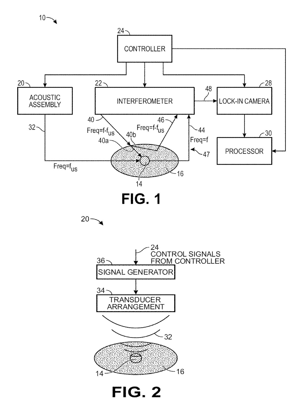
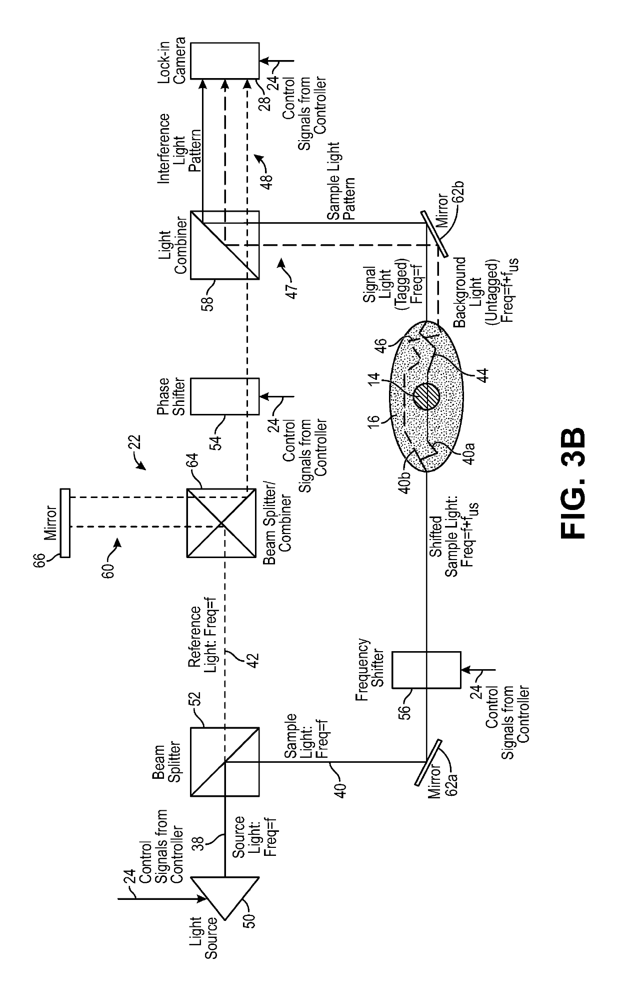
[0052]The ultrasound modulated optical tomography (UOT) systems described herein utilize the combination of a pulsed ultrasound sequence that tags light propagating through an anatomical structure, and a selective lock-in camera that detects the tagged light (e.g., via parallel speckle detection (PSD)), as opposed to a conventional camera, to provide a highly efficient and scalable scheme that enables detection of highly localized and high spatial resolution UOT signals (e.g., blood-oxygen level dependent signals) at great depth inside a biological specimen, e.g., noninvasively through the entire thickness of the human skull and into the underlying cerebral cortical brain matter. The UOT systems may utilize a specific homodyne interference scheme that enables shot noise limited detection of the signal light. Such UOT signals may be used for, e.g., brain-computer interfacing, medical diagnostics, or medical therapeutics. Although the UOT systems are described herein as being used to ...


PUM

PropertyMeasurementUnit
wavelengthaaaaaaaaaa
speedaaaaaaaaaa
wavelengthaaaaaaaaaa

Abstract

A system and method of performing ultrasound modulated optical tomography. Ultrasound is delivered into a target voxel in an anatomical structure, and sample light is delivered into the anatomical structure, whereby a portion of the sample light passing through the target voxel is scattered by the biological tissue as signal light, and a portion of the sample light not passing through the target voxel is scattered by the anatomical structure as background light. The ultrasound and sample light are pulsed in synchrony, such that only the signal light is frequency shifted by the ultrasound. Multiple pulses of the sample light are delivered into the anatomical structure for each pulse of the ultrasound delivered into the target voxel. Reference light is combined with the signal light and background light to generate an interference light pattern, which is sequentially modulated to generate different interference light patterns, which are detected.

Description

RELATED APPLICATION DATA[0001]Pursuant to 35 U.S.C. § 119(e), this application claims the benefit of U.S. Provisional Patent Application Ser. No. 62 / 590,150, filed Nov. 22, 2017, and U.S. Provisional Patent Application Ser. No. 62 / 596,446, filed Dec. 8, 2017, which are expressly incorporated herein by reference. This application is also related to U.S. patent application Ser. No. 15 / 844,370 and U.S. patent application Ser. No. 15 / 844,411, filed on the same date, which are expressly incorporated herein by reference.FIELD OF THE INVENTION[0002]The present invention relates to methods and systems for non-invasive measurements in the human body, and in particular, methods and systems related to detecting physiologically dependent optical parameters in the human body.BACKGROUND OF THE INVENTION[0003]Measuring neural activity in the brain is useful for medical diagnostics, neuromodulation therapies, neuroengineering, or brain-computer interfacing. For example, it may be desirable to measu...

Claims


Application Information

Patent Timeline
Patent Type & Authority Patents(United States)
IPC IPC(8): A61B5/00A61B5/1455G01N21/45G01N21/17
CPCA61B5/0042A61B5/0097A61B5/14553A61B5/4875A61B5/6803G01N21/1702G01N21/45A61B5/7278G01N2021/1706A61B2562/04A61B2576/026A61B5/0066A61B5/0073A61B5/4064A61B5/6814G01N21/4795G01N2021/3129G16H30/40G01B9/02002G01B9/0201G01B9/02031G01N29/2418
Inventor YANG, CHANGHUEIMARBLESTONE, ADAMALFORD, JAMUSOBEK, DANIEL
Owner HI LLC
Why Eureka
Try Eureka