Magnetoresistance effect element

a technology of magnetic effect and element, applied in the field of magnetic effect element, can solve the problems of insufficient mr ratio and reduce the ra to about 0

Active Publication Date: 2019-08-20
TDK CORPARATION
View PDF13 Cites 2 Cited by
  • Summary
  • Abstract
  • Description
  • Claims
  • Application Information

AI Technical Summary

Benefits of technology

[0016]A spinel material including trivalent indium (In) and oxygen has a smaller band gap than a conventional spinel material using Al as a trivalent cation such as MgAl2O4. For this reason, in comparison with the conventional magnetoresistance effect element, the magnetoresistance effect element of the present invention makes possible the discovery that resistance of the tunnel barrier layer is low and a magnetoresistance (MR) ratio is high at a low resistance area (RA).
[0035]Co2Mn1-aFeaAlbSi1-b is a ferromagnetic metal material having high spin polarizability, and a high MR ratio can be obtained compared to other ferromagnetic metal materials.

Problems solved by technology

However, when MgO is used as the non-magnetic insulating layer, it is difficult to reduce the RA to about 0.1 to 0.2 Ω·μm2, and there is a problem that the MR ratio is insufficient even when the RA is reduced.

Method used


Image

  • Magnetoresistance effect element
  • Magnetoresistance effect element
  • Magnetoresistance effect element

Examples


first embodiment

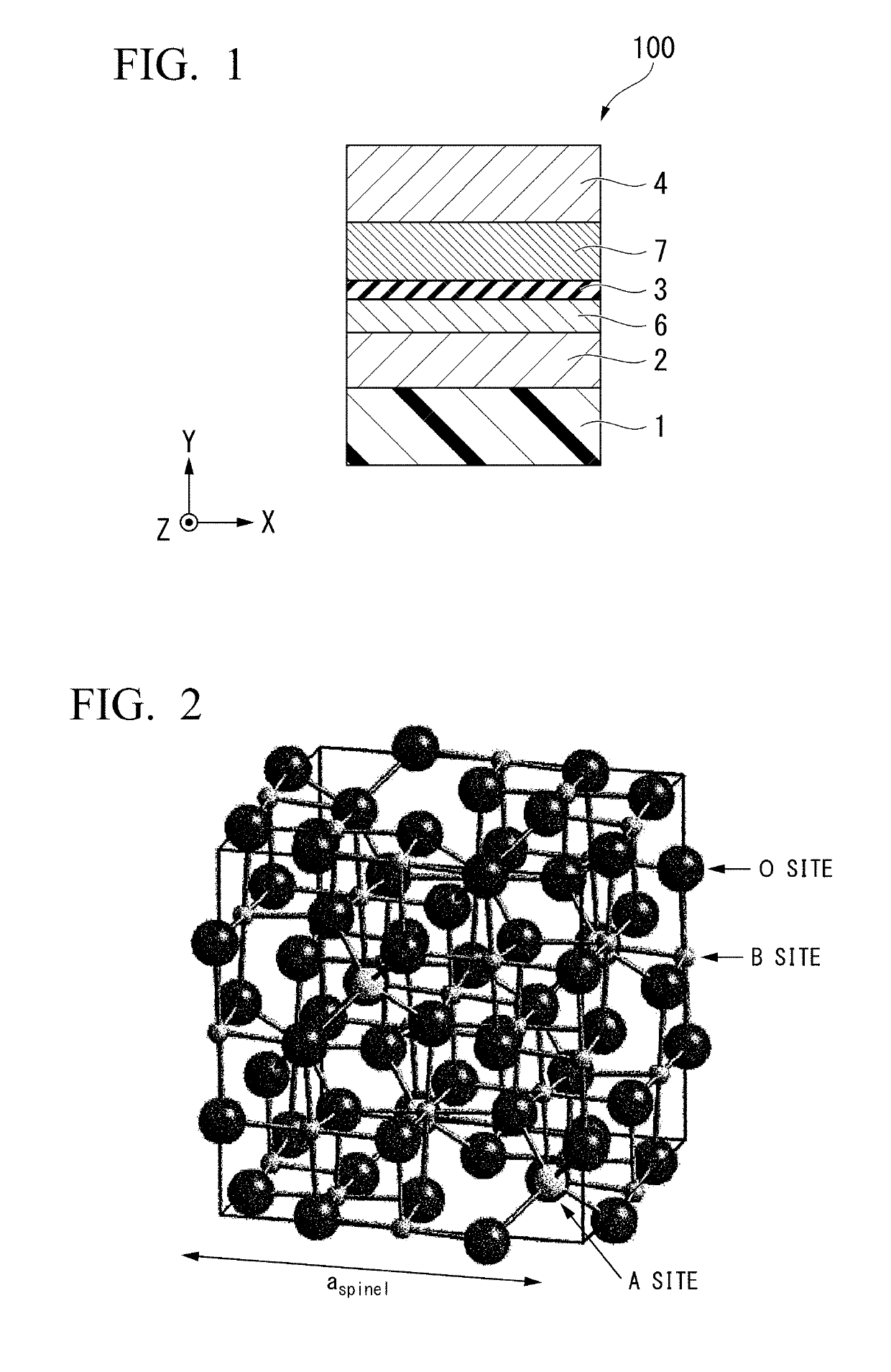
[0049]A magnetoresistance effect element 100 according to the first embodiment will be described. The magnetoresistance effect element 100 has a laminate in which an underlayer 2, a first ferromagnetic metal layer 6, a tunnel barrier layer 3, and a second ferromagnetic metal layer 7 are laminated in that order. The underlayer 2 is made of TiN, VN, or mixed crystals thereof. The tunnel barrier layer 3 is characterized in that it is made of a compound represented by the following composition formula (1) having a spinel structure.

AxIn2Oy  (1)

[0050]In the formula, A is a non-magnetic divalent cation and represents cations of one or more elements selected from the group consisting of magnesium, zinc, and cadmium, x represents a number satisfying 0

(Basic Structure)

[0051]In the example illustrated in FIG. 1, the magnetoresistance effect element 100 is provided on a substrate 1, and is a laminated structure having the unde...

second embodiment

[0093]A difference between a second embodiment and the first embodiment is only a method of forming a tunnel barrier layer. In the first embodiment, the tunnel barrier layer is formed by repeatedly performing formation of a metal film, oxidation, formation of a metal film, and oxidation. In the second embodiment, in the oxidation process, a temperature of the substrate is cooled to −70 to −30° C., and then oxidation is performed. When the substrate is cooled, a temperature gradient occurs between the substrate and a vacuum or between the substrate and plasma. First, when oxygen is brought into contact with a surface of the substrate, it reacts with a metal material and oxidation occurs. However, since the temperature is low, oxidation does not proceed. Accordingly, it is easy to adjust an amount of oxygen in the tunnel barrier layer. In addition, when the temperature gradient is formed, it is easy to adjust epitaxial growth (lattice-matched growth). Since crystal growth proceeds acc...

example 1

[0100]Hereinafter, an example of the method of producing the magnetoresistance effect element according to the first embodiment will be described. Film formation was performed on the substrate 1 on which a thermally oxidized silicon film was provided using a magnetron sputtering method. First, TiN acting as the underlayer 2 was formed on the upper surface of the substrate 1 at 4 nm. The underlayer 2 was obtained by using a Ti target as a target, forming a film of about 10 nm according to the reactive sputtering method using a mixed gas including Ar and nitrogen at a ratio of 1:1 as sputtering gas, and polishing the film using a CMP method to reach the thickness. Next, CoFe was formed on the underlayer 2 as the first ferromagnetic metal layer 6 at 5 nm.

[0101]Next, the tunnel barrier layer 3 was formed on the first ferromagnetic metal layer 6. The method of forming the tunnel barrier layer 3 was as follows. A target having a composition of an MgIn2 alloy was sputtered, and MgIn2 was f...


PUM


Abstract

Provided is a magnetoresistance effect element that that generates a high MR ratio at a lower RA than a TMR element using a material of a conventional tunnel barrier layer or MgAl2O4. The magnetoresistance effect element includes a laminate in which an underlayer, a first ferromagnetic metal layer, a tunnel harrier layer, and a second ferromagnetic metal layer are laminated in that order, wherein the underlayer is made of TiN, NbN, TaN, ZrN or mixed crystals thereof, and the tunnel barrier layer is made of a compound that has a spinel structure and expressed by composition formula (1) below: (1) AxIn2Oy, where A is the non-magnetic divalent cation and represents cations of one or more elements selected from the group consisting of magnesium and zinc, x represents a number satisfying 0<x≤2, and y represents a number satisfying 0<y≤4.

Description

BACKGROUND OF THE INVENTION[0001]Field of the Invention[0002]The present invention relates to a magnetoresistance effect element.[0003]Priority is claimed on Japanese Patent Application No. 2016-192010, filed Sep. 29, 2016, the content of which is incorporated herein by reference,[0004]Description of Related Art[0005]A giant magnetoresistance (GMR) element that is made of a multilayer film of a ferromagnetic layer and a non-magnetic layer and a tunnel magnetoresistance (TMR) element that uses an insulating layer (a tunnel barrier layer or a barrier layer) for a non-magnetic layer are known (JP5586028B, US2013-0221461-A, APPLIED PHYSICS LETTERS 96, 212505 (2010), Applied Physics Letters, 105, 242407 (2014), Physical Review B 86, 024426 (2012), and IEEE Trans Magn., Vol. 46, No. 6, 2086 (2010)). In general, the TMR element has higher element resistance than the GMR element, whereas a magnetoresistance (MR) ratio of the TMR element is greater than that of the GMR element, TMR elements ...

Claims


Application Information

Patent Timeline
Patent Type & Authority Patents(United States)
IPC IPC(8): G11C11/16H01L43/08H01L43/10H01L43/12H01L43/02H01L27/22
CPCH01L43/08G11C11/161H01L43/10H01L43/12H01L43/02H01L27/222H10N50/85H10N50/10H10B61/00H10N50/01H10N50/80
Inventor SASAKI, TOMOYUKI
Owner TDK CORPARATION
Why Eureka
Try Eureka