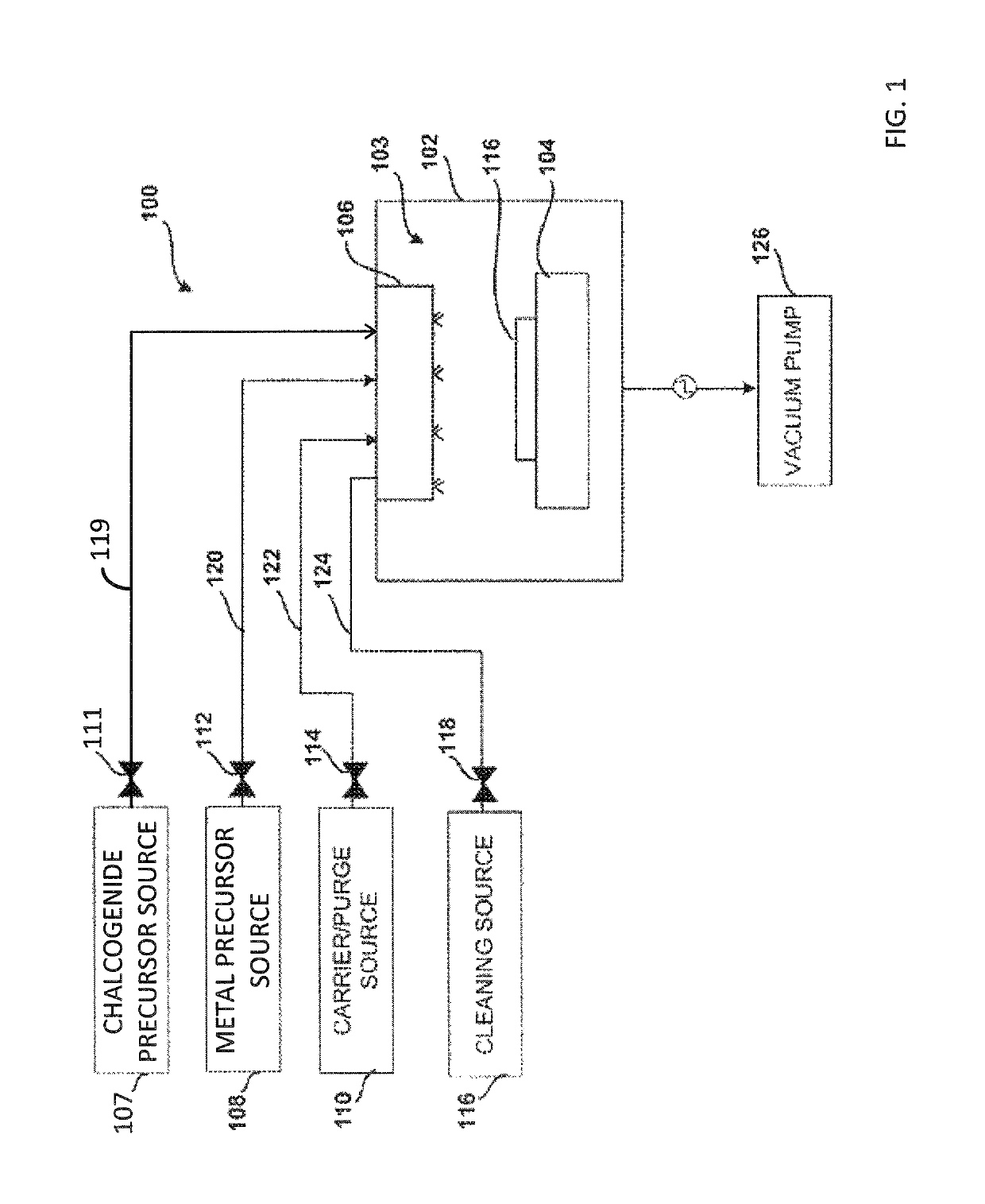
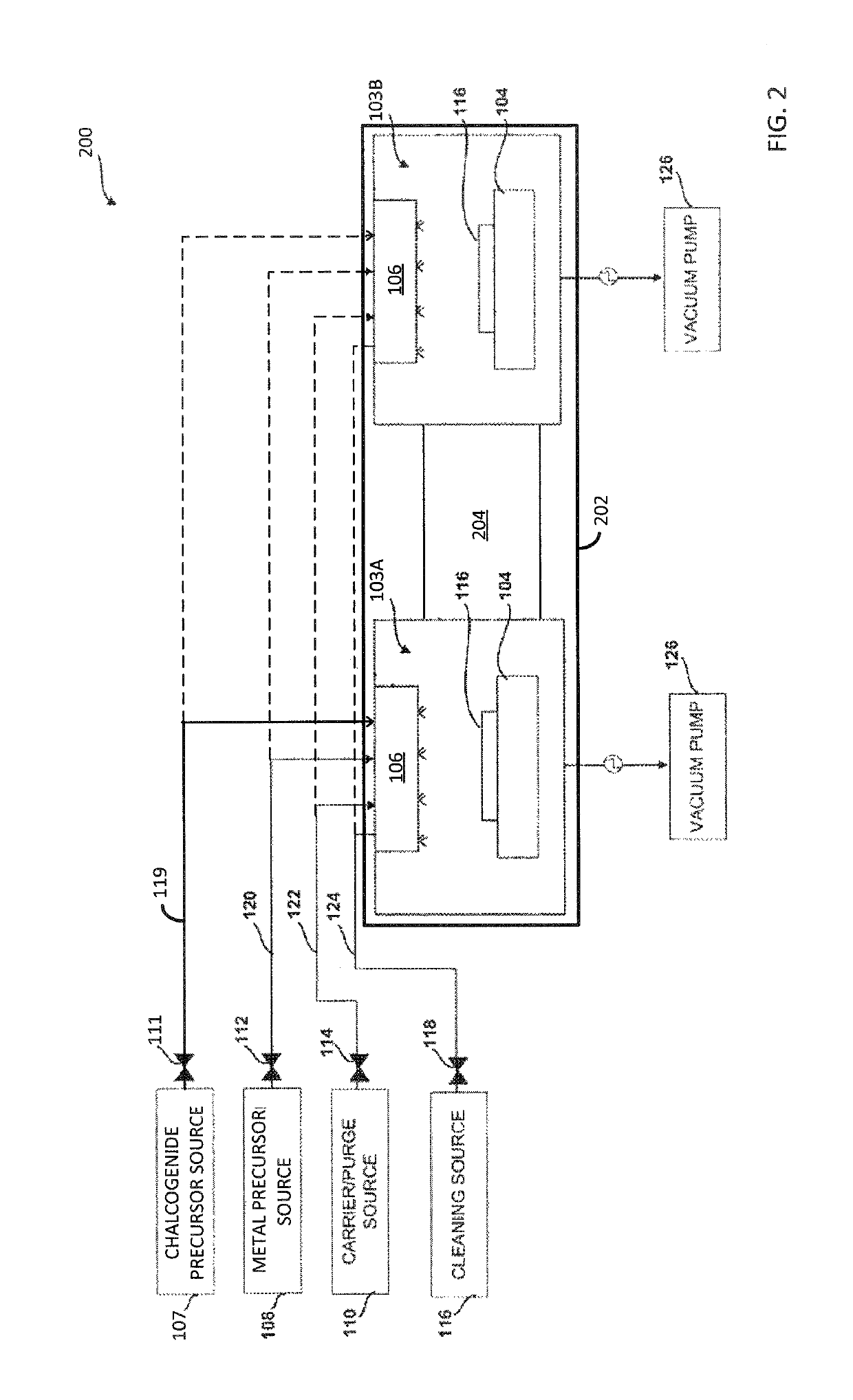
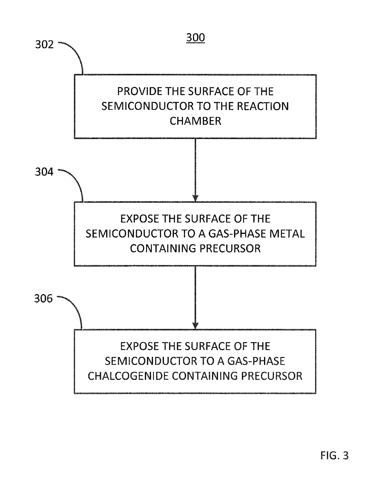
Method for passivating a surface of a semiconductor and related systems

a technology of semiconductor and surface, applied in the direction of chemical vapor deposition coating, coating, basic electric elements, etc., can solve the problems of unfavorable device performance, unfavorable device performance, and difficulty in integration of immersion based passivation process into vacuum or gas-phase deposition system used for subsequent dielectric material deposition

Active Publication Date: 2019-09-10
ASM IP HLDG BV
View PDF2958 Cites 197 Cited by
  • Summary
  • Abstract
  • Description
  • Claims
  • Application Information

AI Technical Summary

Problems solved by technology

Unfortunately, the interface between the channel region of the device, formed of high-mobility semiconductor materials such as germanium, silicon germanium or III-V semiconductor materials, and the gate dielectric (e.g., high dielectric constant (k) materials) typically includes a large interface trap density (Dit).
The high Dit values are thought to result from vacancies and dangling bonds at the surface of the high-mobility semiconductor material, and the high Dit values deleteriously affect the performance of devices formed with the high-mobility materials and provide a technical challenge to the development of complementary metal oxide semiconductor (CMOS) devices using such high-mobility semiconductor materials.
However, the immersion based passivation process is difficult to integrate into a vacuum or gas-phase deposition system used for subsequent dielectric material deposition.
Consequently, there is an undesired air exposure time following sulfur passivation using wet chemical solution techniques and prior to the subsequent deposition of the dielectric material.
This air exposure can severely affect the device performance, since the passivation layer cannot fully prevent oxide regrowth during this exposure, and oxide growth on germanium, silicon germanium and III-V semiconductor surfaces generally increases Dit.
Additionally, performing solution-based passivation at elevated temperatures (e.g., >100° C.) is problematic.
However, such passivation processes may be non-ideal as the processes may in general leave a defected semiconductor surface due to incomplete passivation of the semiconductor surface.

Method used


Image

  • Method for passivating a surface of a semiconductor and related systems
  • Method for passivating a surface of a semiconductor and related systems
  • Method for passivating a surface of a semiconductor and related systems

Examples


Embodiment Construction

[0017]Although certain embodiments and examples are disclosed below, it will be understood by those in the art that the invention extends beyond the specifically disclosed embodiments and / or uses of the invention and obvious modifications and equivalents thereof. Thus, it is intended that the scope of the invention disclosed should not be limited by the particular disclosed embodiments described below.

[0018]As used herein, the term “surface” may refer to any portion of an exposed semiconductor surface. For example, the surface may be the entire exterior of a semiconductor substrate and / or layer or a portion thereof or a top surface of a semiconductor substrate and / or layer thereon or a portion of either.

[0019]As used herein, the term “chalcogenide containing precursor” may refer to a precursor containing a chalcogen and a more electropositive element or radical. A chalcogen is an element from the group VI of the periodic table including oxygen, sulphur, selenium, tellurium and polon...


PUM

PropertyMeasurementUnit
temperaturesaaaaaaaaaa
temperatureaaaaaaaaaa

Abstract

A system and a method for passivating a surface of a semiconductor. The method includes providing the surface of the semiconductor to a reaction chamber of a reactor, exposing the surface of the semiconductor to a gas-phase metal containing precursor in the reaction chamber and exposing the surface of the semiconductor to a gas-phase chalcogenide containing precursor. The methods also include passivating the surface of the semiconductor using the gas-phase metal containing precursor and the gas-phase chalcogenide containing precursor to form a passivated surface. The system for passivating a surface of a semiconductor may include a reactor, a metal containing precursor source fluidly coupled to the reactor, and a chalcogenide containing precursor source fluidly couple to the reactor, wherein the metal containing precursor source provides a gas-phase metal containing precursor to a reaction chamber of the reactor, and wherein the chalcogenide containing precursor source provides a gas-phase chalcogenide containing precursor to a reaction chamber of the reactor.

Description

FIELD OF INVENTION[0001]The present disclosure generally relates to methods for passivating a surface of a semiconductor and also to systems for passivating a surface of a semiconductor.BACKGROUND OF THE DISCLOSURE[0002]High-mobility semiconductors, such as germanium, silicon germanium and compound semiconductors (e.g., III-V compound semiconductors) may be desirable to use in the fabrication of semiconductor devices because of their relatively high electron and / or hole mobility. Devices formed with high-mobility semiconductor materials may theoretically exhibit better performance, faster speeds, reduced power consumption, and have higher breakdown fields compared to similar devices formed with a lower-mobility semiconductor, such as silicon.[0003]High-mobility semiconductor material may be used, for example, to fabricate metal oxide field effect (MOSFET) devices. A typical MOSFET device includes a source region, a drain region, and a channel region, each formed of a semiconductor m...

Claims


Application Information

Patent Timeline
Patent Type & Authority Patents(United States)
IPC IPC(8): H01L21/02H01L23/29C23C16/30H01L21/67H01L23/31H01L21/306C23C16/455H01L29/66
CPCH01L23/3171C23C16/305C23C16/45544C23C16/45553H01L21/02178H01L21/02205H01L21/02312H01L21/306H01L21/67017H01L21/6719H01L23/291H01L21/02271H01L29/66477H01L21/67155H01L21/28247H01L21/02568H01L21/02041
Inventor JIANG, XIAOQIANGTANG, FUXIE, QICALKA, PAULINEJUNG, SUNG-HOONGIVENS, MICHAEL EUGENE
Owner ASM IP HLDG BV
Why Eureka
Try Eureka