

Catalyst for hydrogen peroxide decomposition, process for producing the same, and method for decomposing hydrogen peroxide using the catalyst
a hydrogen peroxide and catalyst technology, applied in the direction of physical/chemical process catalysts, metal/metal-oxide/metal-hydroxide catalysts, treatment water, etc., can solve the problems of reduced treatment function and difficulty in separating the sediment yielded by neutralization, and achieves less apt to dissolve away, reduces the effect of oxidation rate and low cos
- Summary
- Abstract
- Description
- Claims
- Application Information
AI Technical Summary
Benefits of technology
Problems solved by technology
Method used
Image

Examples
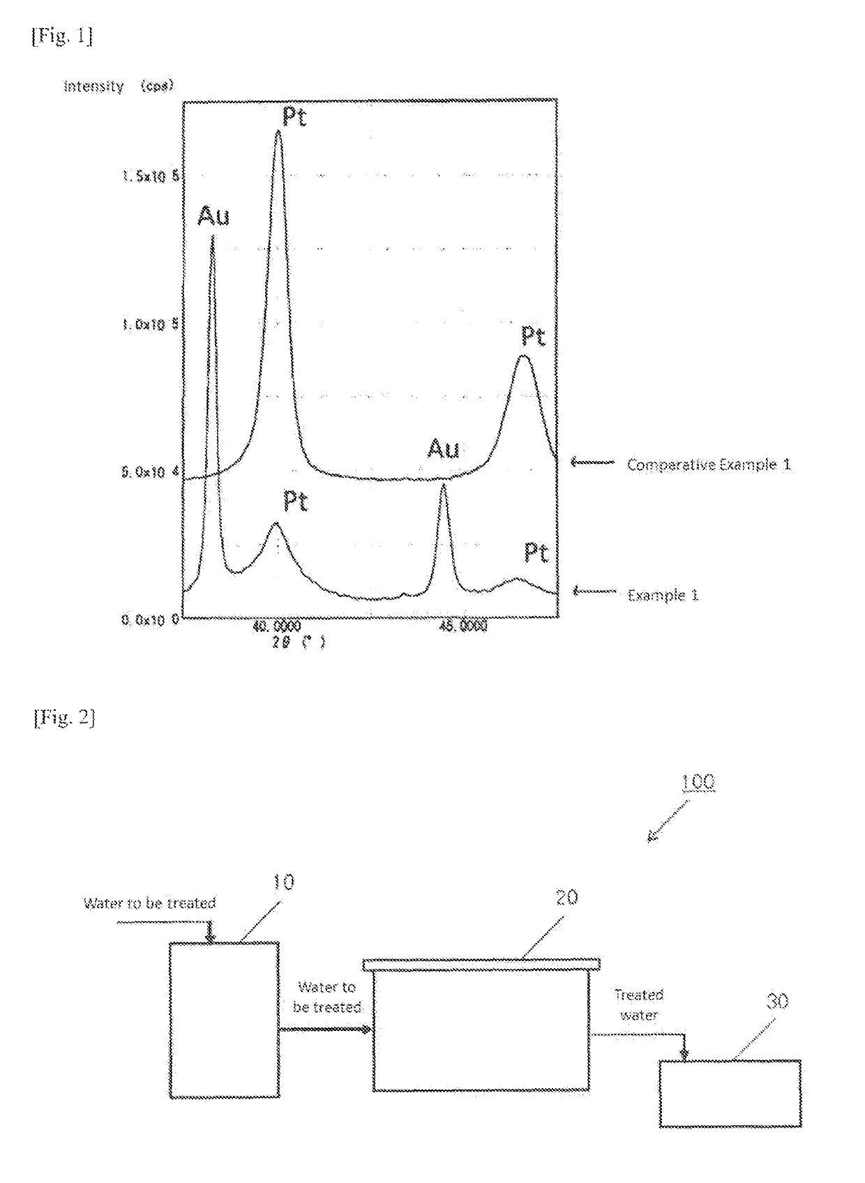
example 1
(Base)
[0084]A plate made of Zr and having a rectangular shape of 50 mm (width)×70 mm (thickness)×1 mm (length) was used as a base.
(Plating Solution for Forming Amorphous Catalyst Layer)
[0085]A plating solution containing 0.3% by mass Pt and 6.0% by mass W and having a pH of 7 was prepared. The plating solution was obtained by dissolving chloroplatinic acid and sodium tungstate respectively as Pt and W sources in water.
(Plating Solution for Interlayer Formation)
[0086]As the plating solution, use was made of a neutral solution manufactured by EEJA (product: Au plating solution in Temperex Series).
(Pretreatment of the base)
[0087]The base was subjected successively to degreasing with a commercial alkali and an immersion treatment with a fluoride-based acid, thereby activating the surface of the base.
(Formation of Interlayer)
[0088]The pretreated base was subjected to electroplating using the plating solution for interlayer formation. The electroplating conditions included a current densi...
examples 2 and 3
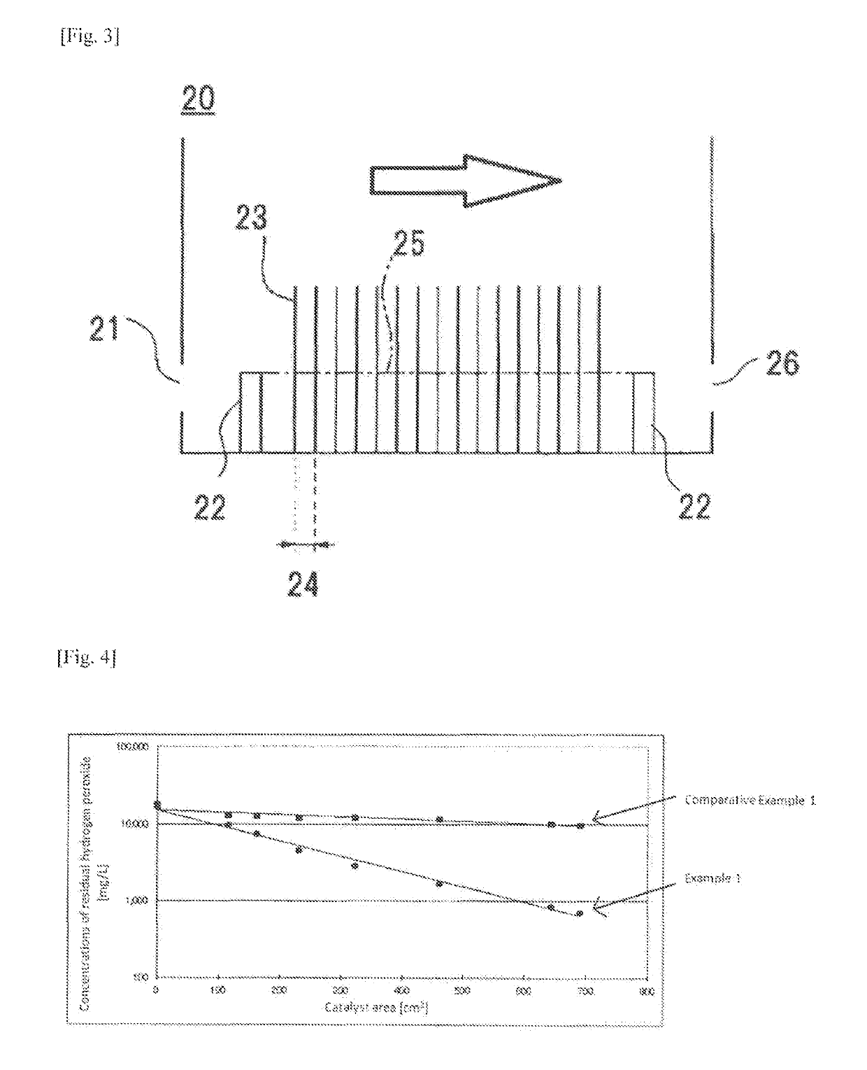
[0109]The hydrogen peroxide decomposition performance of catalysts was ascertained in the same manner as in Example 1, except that the water to be treated had the sulfuric acid concentrations shown in Table 3 and that the catalyst surface areas shown in Table 3 were used to conduct the water treatment. The results are shown in Table 3.
[0110]
TABLE 3Sulfuric acidCatalyst surface areaconcentration[cm2][mass %]0115161230322460Example 28Concentration[mg / L]17,8002,2001,400900600400of residualmass %1.780.220.140.090.060.04H2O2Example 344Concentration[mg / L]16,8005,8003,7002,0001,200650of residualmass %1.680.580.370.200.120.07H2O2Sulfuric acidCatalyst surface areaconcentration[cm2][mass %]6446908059209661,150Example 28Concentration[mg / L]20017014012010040of residualmass %0.020.0170.0140.0120.0100.004H2O2Example 344Concentration[mg / L]370340270200200170of residualmass %0.040.0340.0270.0200.0200.017H2O2
[0111]It was found from the results given in Table 3 that even in the case where the water to ...
example 4
(Base)
[0112]A plate made of Zr (punching metal) which had a rectangular shape of 48 mm (length)×80 mm (width)×0.7 mm (thickness) and in which holes having a diameter of 3 mm with an interval of 6 mm had been formed by punching was used as a base.
(Plating Solution for Forming Amorphous Catalyst Layer)
[0113]A plating solution containing 0.3% by mass Pt and 6.0% by mass W and having a pH of 7 was prepared as in Example 1. The plating solution was obtained by dissolving chloroplatinic acid and sodium tungstate respectively as Pt and W sources in water.
(Plating Solutions for Interlayer Formation)
[0114]As the plating solutions, use was made of an acidic Pt plating solution and a neutral Au plating solution manufactured by EEJA (product: Temperex 401).
(Pretreatment of the Base)
[0115]The base was subjected successively to degreasing with a commercial alkali, an immersion treatment with a fluoride-based acid, etc., thereby activating the surface of the base.
(Formation of Interlayer)
[0116]The...
PUM
| Property | Measurement | Unit |
|---|---|---|
| thickness | aaaaa | aaaaa |
| particle diameter | aaaaa | aaaaa |
| particle diameter | aaaaa | aaaaa |
Abstract
Description
Claims
Application Information