Flexible composite duct for the transport of cryogenic fuels and oxidizers

a composite duct and oxidizer technology, applied in the field of composite ducts, can solve the problems of heavy weight, damage or failure, weak and brittleness of most non-metallic materials, etc., and achieve the effects of low cost, high performance and low weigh

Active Publication Date: 2020-04-07
UNITED LAUNCH ALLIANCE
View PDF30 Cites 1 Cited by
  • Summary
  • Abstract
  • Description
  • Claims
  • Application Information

AI Technical Summary

Benefits of technology

[0010]The present disclosure solves the foregoing problems. According to aspects of the present disclosure, multi-ply composite duct comprised of polymeric materials, inter-ply cryogenic epoxy or sealing agent, and structural reinforcement material demonstrates the ability to satisfy performance requirements for transfer of single and multiphase fluids at cryogenic temperatures as low as −452 degrees Fahrenheit and as high as +200 degrees Fahrenheit. Embodiments made according to the present disclosure offer a high performance, low cost, low weight alternative to all metallic cryogenic ducting. Cryogenic ducting must have strength, resilience, and flexibility at these conditions. For example, in some applications, the duct must withstand substantial vibration arising from different inputs as well as inhibit the transfer of such vibrations to surrounding vehicle structures. The duct must also minimize out-gassing in environments where sensitive equipment and / or composite vehicle structures are present and must be compatible with a wide range of fuels and oxidizers within this temperature range. For launch vehicle and spacecraft applications, mass and the resulting interface loads are critical to vehicle performance.
[0011]According to aspects of the present disclosure, in one embodiment, the invention is a composite construction comprised of multiple layers or plies of polymer film with an inter-ply cryogenic epoxy or adhesive agent that significantly increases the strength of the duct while maintaining flexibility. The epoxy used in the construction of the duct is an aerospace grade adhesive used in applications in which low out-gassing is a requirement. An integral structural plastic, polymer, or metallic wire reinforces the duct while preventing duct occlusion or collapse in the event of delamination or puncture of the inner plies and enhancing three-dimensional shape memory by contributing to the return of the duct to its original shape following vibration and / or torsion events. The wire may take the form of a coil, individual rings, or a combination of both. Additional reinforcement may be added to the ends of the duct to minimize point loading and stress concentrations induced at the system interface. In all of these iterations, the result is a robust design tolerant of mechanical environments and damage.
[0012]According to aspects of the present disclosure, in one embodiment the duct may comprise two layers of polymer film with an inner layer of epoxy. It may also comprise up to ten layers of polymer with inner epoxy layers between each polymer layer. The epoxy bonds the adjacent polymer layers continuously along the length of the duct. The continuous bond of adjacent polymer surfaces resists occlusion, perforation and collapse. Adhesive bonding along the axial length of the duct joining adjacent polymer surfaces acts as a reinforcement and fluid barrier. The bonded structure of the invention also prevents inclusions of gas and liquid from accumulating if a layer is punctured, and mitigates the risk of occlusion of the duct if flow is allowed to enter the interstitial space between layers. The absence of gaps and / or spaces between layers prevents occlusion arising from trapped gases or liquids, particularly as a result of significant pressure changes that arise during vehicle ascent or in the space environment. The bonded multi-ply construction also reduces or mitigates the propagation of cracks that may form in the duct wall.

Problems solved by technology

Cryogenic temperatures are problematic for non-metallic materials because of the resulting poor properties, making most non-metallic materials weak and brittle.
However metallic solutions tend to be massive or require massive support systems in order to survive significant loading environments.
The higher mass when combined with high vibration and other loads arising from launch and space vehicle environments can further result in high loads transferred to adjacent structures leading to damage or failure.
Adjacent structures can include sensitive structural or payload elements, which can drive the need for additional supports or similar mitigations resulting in even more total system mass.
However bellows type solutions present new challenges such as squirm, bulging and fatigue induced by high vibration and load environments.
Again, this leads to increasingly complex designs with increased expense and do not reduce weight in an appreciable or meaningful way and in some instances increase weight.
Metallic ducts can present additional challenges such as galvanic corrosion and combustion when transporting pressurized oxygen.
These and similar issues further result in more complex designs which increase expense and do not reduce weight in an appreciable or meaningful way.
The metals forming the duct and coil could cause galvanic corrosion.
Moreover, the fabric layer, at a minimum, is a significant fire hazard.
If the duct or hose contains pressurized cryogenic oxygen, an impact or puncture of duct or hose can result in combustion and explosion and the presence of the fabric layers facilitate and enhance this risk.
Again, the cloth layers make this hose a significant combustion risk.
Moreover, while the patent states the hose will remain flexible at temperatures down to −196 degrees Centigrade (approximately −320 degrees Fahrenheit), it does not teach or suggest the ability to handle cryogenic liquids below −320 degrees Fahrenheit.
Further still, hoses of the type described in the '429 publication and '543 patent present a further risk of perforation and / or occlusion.
Fluid accumulation in this interstitial gap also may rupture the hose, particularly as the ambient pressure decreases during vehicle ascent or approaches zero in the space environment.
As a result, these hoses would not have applicability at temperatures below approximately −300 degrees Fahrenheit because at temperatures below −300 degrees, the air would condense.
In addition to damage resulting from vibrations or load transfer, payloads and composite structures can be damaged by outgas emanating from polymers and epoxies.
This observation, in addition to the afore described specific failure scenarios, do not allow for these designs or any practical variants to be used for launch or space system applications.

Method used


Image

  • Flexible composite duct for the transport of cryogenic fuels and oxidizers
  • Flexible composite duct for the transport of cryogenic fuels and oxidizers
  • Flexible composite duct for the transport of cryogenic fuels and oxidizers

Examples


Embodiment Construction

[0039]Those of skill in the art will recognize that the following description is merely illustrative of the principles of the invention, which may be applied in various ways to provide many different alternative embodiments. This description is made for illustrating the general principles of the teachings of this invention and is not meant to limit the inventive concepts disclosed herein. The detailed description is to be construed as exemplary only and does not describe every possible embodiment since describing every possible embodiment would be impractical, if not impossible. Numerous alternative embodiments could be implemented, using either current technology or technology developed after the filing date of this patent, which would still fall within the scope of the claims.

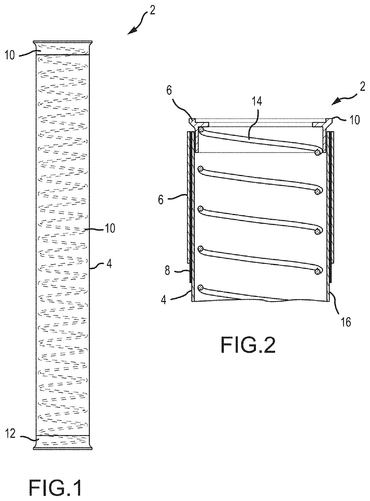
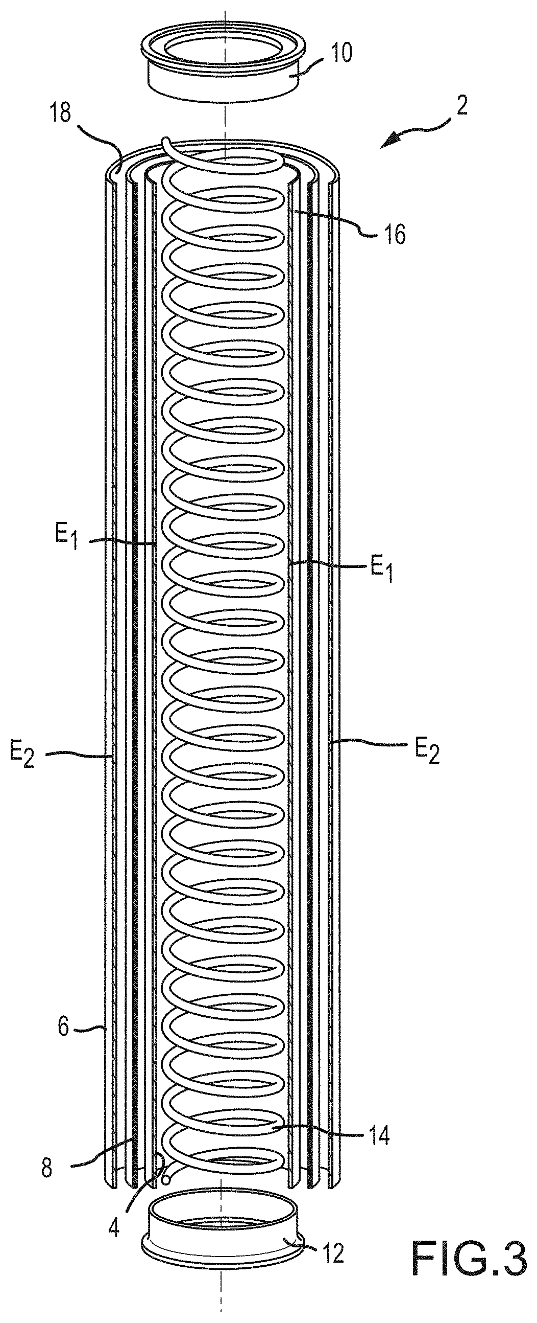
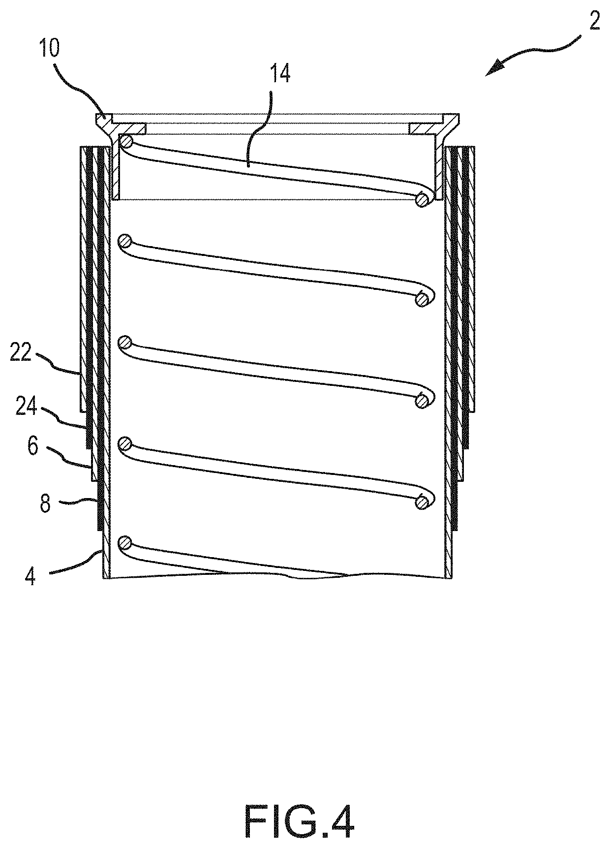
[0040]Turning to FIGS. 1-3, a first embodiment of a multi-ply polymeric duct 2 according to aspects of the invention is disclosed. As illustrated, the duct comprises a first innermost polymeric sheet 4, a sec...


PUM

PropertyMeasurementUnit
thicknessaaaaaaaaaa
thicknessaaaaaaaaaa
thicknessaaaaaaaaaa

Abstract

A multi-ply composite duct comprised of polymeric materials, inter-ply cryogenic epoxy or sealing agent, and structural reinforcement material and methods of making the duct are disclosed. Ducts according to the present disclosure demonstrate the ability to satisfy performance requirements for transfer of single and multiphase fluids at cryogenic temperatures, and resist perforation, occlusion, combustion and galvanic coupling.

Description

CROSS-REFERENCE TO RELATED APPLICATIONS[0001]This application claims the benefit of U.S. Provisional Patent Application Ser. No. 62 / 434,918, filed Dec. 15, 2016, the entirety of which is incorporated herein by reference.FIELD OF THE INVENTION[0002]Embodiments of the present invention generally relate to composite ducts capable of handling fluids at a wide range of temperatures, including cryogenic temperatures, and more specifically, to composite ducts used with cryogenic propellants in the dynamic environment of a launch vehicle.BACKGROUND OF THE INVENTION[0003]Launch and Space vehicle systems utilize propellants maintained at cryogenic temperatures. Cryogenic temperatures include as low as −452 degrees Fahrenheit. As one example, liquid hydrogen and liquid oxygen are stored in separate propellant tanks and combined at the inlet of an engine prior to combustion. Not only must the propellants be stored and maintained at extremely cold temperatures, but to supply the engine(s) with l...

Claims


Application Information

Patent Timeline
Patent Type & Authority Patents(United States)
IPC IPC(8): F16L59/14F16L59/153
CPCF16L59/141F16L59/153B32B1/08B32B27/08B32B27/281B32B27/322B32B27/38B32B2307/50B32B2307/72B32B2307/732B32B2597/00F16L11/06F16L11/10
Inventor CAMPBELL, CONNOR W.KAYNE, GUY BRENDANKRAJNAK, JAMES A.
Owner UNITED LAUNCH ALLIANCE
Why Eureka
Try Eureka