Chalcogenide glass waveguides for refractive non-mechanical beam steerer

a technology of chalcogenide glass and waveguides, applied in non-linear optics, instruments, optics, etc., can solve the problems of high repair and replacement costs, slow scan rate, short lifetime before mechanical failure, etc., and achieve low optical loss, low absorption loss, and low absorption loss

Active Publication Date: 2020-06-23
THE UNITED STATES OF AMERICA AS REPRESENTED BY THE SECRETARY OF THE NAVY
View PDF8 Cites 0 Cited by
  • Summary
  • Abstract
  • Description
  • Claims
  • Application Information

AI Technical Summary

Benefits of technology

[0013]There are several advantages with the present invention. It permits the continuous, agile steering of MWIR light in a low-SWaP package. The ChG waveguides have low absorption throughout the MWIR and thus permit low optical losses. The LC alignment layer aligns the LC uniformly, has low absorption losses, and minimizes scattering losses at the LC / core interface. This technology can be used for mapping atmospheric constituents with MWIR lasers.

Problems solved by technology

To date, beam steering has typically relied on mechanical devices such as gimbal-mounted mirrors or rotating Risley prisms which have inherent issues including large size, weight, and power (SWaP) requirements, slow scan rates, high repair and replacement costs, and short lifetimes before mechanical failure.
Several technologies have previously been demonstrated for non-mechanical beam steering (NMBS), but each has significant drawbacks.
OPAs suffer from power in side lobes resulting from diffractive effects.
Further, they typically operate at a fixed wavelength, so wavelength variation within a spectral band or sub-band is not possible without multiple devices.
These devices are reflective arrays that achieve steering by controlling the phase at each pixel, and, like OPA's, are subject to diffractive effects.
They also suffer from large chromatic dispersion and may require bulky optics for beam expansion and compression.
These devices suffer from limitations on power handling due to thermal issues and have limited maximum theoretical efficiency due to the binary operation of the micromirrors.
These devices, are highly efficient, with >99.5% diffraction efficiency, and have low absorption loss (<2% for visible through SWIR wavelengths) but are limited to discretized steering.
As a result of the limitations described above, none of these existing technologies on its own offers the characteristics required for agile, low SWaP and continuous steering.

Method used


Image

  • Chalcogenide glass waveguides for refractive non-mechanical beam steerer
  • Chalcogenide glass waveguides for refractive non-mechanical beam steerer
  • Chalcogenide glass waveguides for refractive non-mechanical beam steerer

Examples


Embodiment Construction

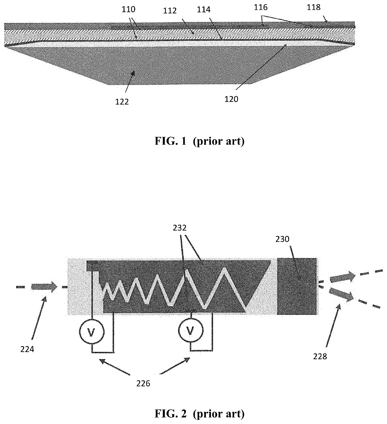
[0025]The prevent invention relates to SEEOR devices in which the waveguide core, subcladding, or both comprise ChG. ChGs are amorphous semiconductors that contain as a major constituent one or more of the “chalcogen” elements from group 6a of the periodic table (sulfur, selenium and tellurium), covalently bonded to network formers, such as, Ge, Sb, Ga, etc. (Zakery et al., “Optical properties and applications of chalcogenide glasses: a review,” J. Non-Cryst. Solids, 330, 1-12 (2003)). They have low phonon energy in comparison to most common optical materials and can thus have transmission extending through the MWIR.

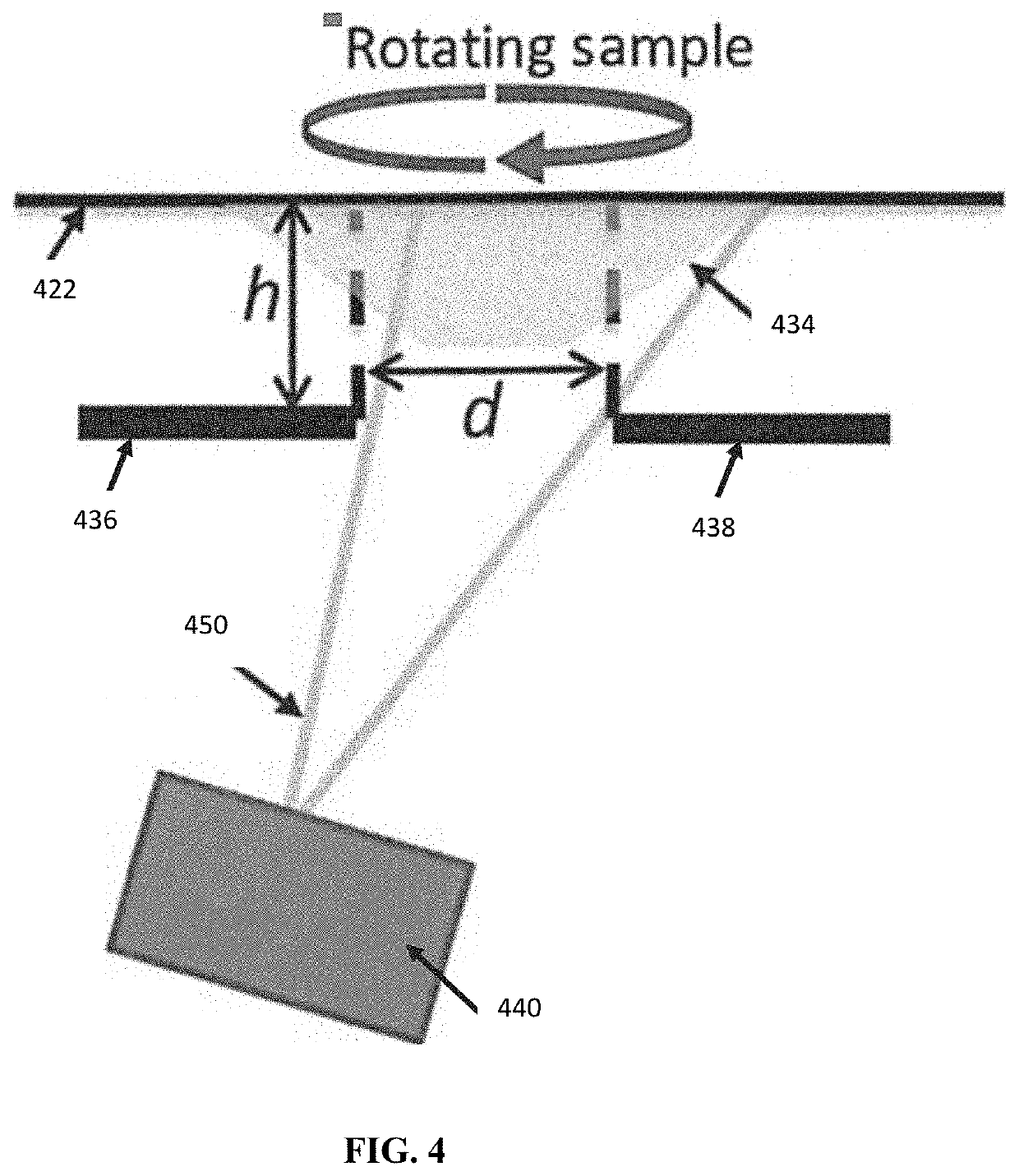
[0026]In one embodiment (illustrated in FIG. 4), the tapered subcladding is produced by the following method: a shadow mask with two halves (Mask 1 436 and Mask 2 438) in which the opening is a slit with a width, d, is positioned a fixed distance, h, from the substrate 422. A deposition source 440 with a flux 450 is used to deposit the subcladding. The resulting film has...


PUM

PropertyMeasurementUnit
taper angleaaaaaaaaaa
wavelengthsaaaaaaaaaa

Abstract

A method for making a chalcogenide glass waveguide in a liquid crystal-based non-mechanical beam steering device that permits steering in the mid-wave infrared. The waveguide core, the subcladding, or both comprise a chalcogenide glass. A mask is used to produce a tapered subcladding. Also disclosed is the related non-mechanical beam steering device that includes a chalcogenide waveguide.

Description

PRIORITY CLAIM[0001]The present application is a non-provisional application claiming the benefit of U.S. Provisional Application No. 62 / 481,734 filed on Apr. 5, 2017 by Jesse A. Frantz et al., entitled “CHALCOGENIDE GLASS WAVEGUIDES FOR REFRACTIVE NON-MECHANICAL BEAM STEERER,” the entire contents of which is incorporated herein by reference.BACKGROUND OF THE INVENTIONField of the Invention[0002]The present invention relates to chalcogenide glass (ChG) waveguides and more specifically to ChG waveguides for use in a liquid crystal (LC) non-mechanical beam steerer.Description of the Prior Art[0003]The midwave infrared (MWIR) portion of the electromagnetic spectrum, typically defined as light having wavelengths ranging from 3-5 μm, is critical for a variety of application. For example, the MWIR is a critical band for the detection of a variety molecular species, which have distinct vibrational absorptions in this range. Mapping in this spectral range, e.g. in a MWIR LIDAR configuration...

Claims


Application Information

Patent Timeline
Patent Type & Authority Patents(United States)
IPC IPC(8): G02F1/01G02F1/1343G02F1/1337G02F1/295C03C3/32C03C13/04G02F1/29G02F1/00G02F1/13
CPCG02F1/2955G02F1/1326G02F1/134309C03C3/321G02F1/011G02F1/1337G02F1/292C03C13/043G02F1/0018G02F2001/0113G02F2203/24G02F1/0113
Inventor FRANTZ, JESSE A.MYERS, JASON D.BEKELE, ROBEL Y.SPILLMANN, CHRISTOPHER M.NACIRI, JAWADKOLACZ, JAKUBGOTJEN, HENRY G.AUXIER, JASONSHAW, LESLIE BRANDONSANGHERA, JASBINDER S.
Owner THE UNITED STATES OF AMERICA AS REPRESENTED BY THE SECRETARY OF THE NAVY
Why Eureka
Try Eureka