
Light source unit

a technology of light source and light source, which is applied in the direction of lighting and heating apparatus, planar/plate-like light guides, instruments, etc., can solve the problems of reduced frontal luminance, worse contrast between black display portions and white display portions, etc., and achieve excellent contrast and high luminance

Active Publication Date: 2020-08-04
TORAY IND INC
View PDF35 Cites 2 Cited by
  • Summary
  • Abstract
  • Description
  • Claims
  • Application Information

AI Technical Summary

Benefits of technology

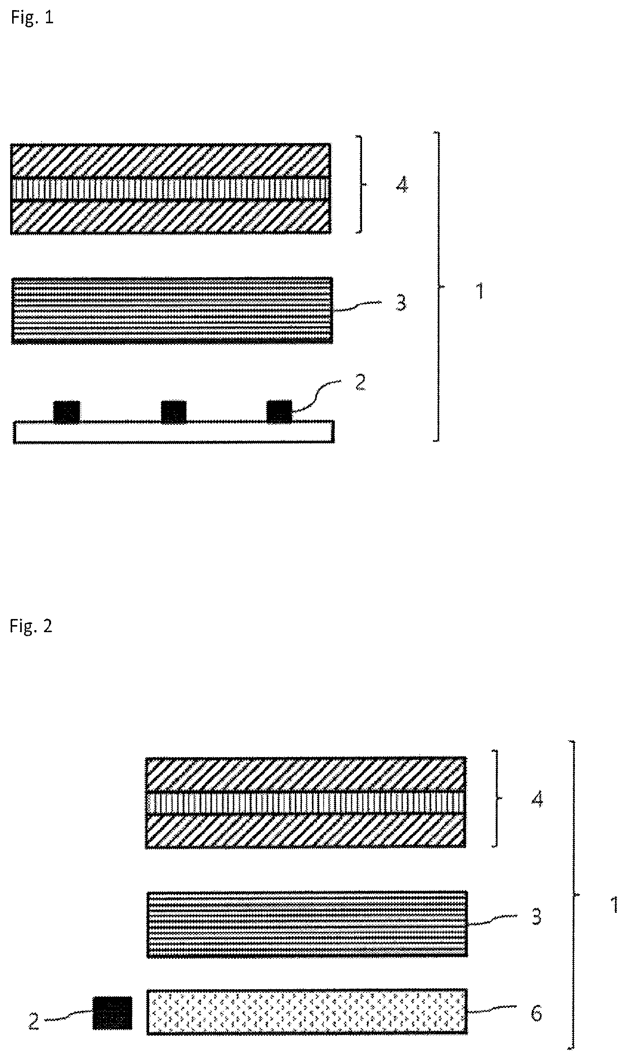
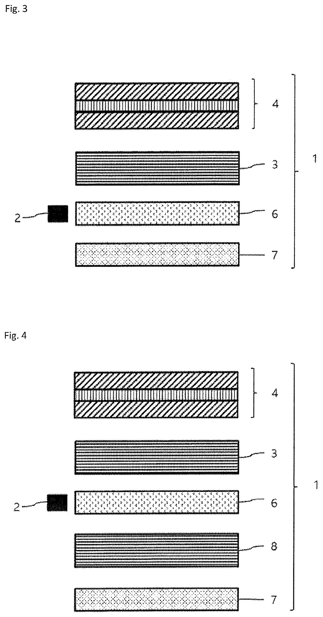
The present invention aims to provide a light source unit that can improve the contrast between black and white display portions and enhance the frontal luminance when mounted on a display. This is achieved by partially turning off LEDs based on the image on the screen to improve whitish color, while avoiding light leakage into the areas where the light source is turned off to display black. Ultimately, this results in a light source unit that can create an excellent display both in terms of contrast and luminance.

Problems solved by technology

However, light from a light source travels divergently toward a person who sees the light, which means that the light is emitted not only in the frontal direction but also in oblique directions, and accordingly, the light leaks divergently into the portions in which the light of the light source is originally turned off to display a black color, posing problems in that the contrast is worsened between the black display portions and the white display portions and that the frontal luminance is also reduced.

Method used


Image

  • Light source unit
  • Light source unit
  • Light source unit

Examples


synthesis example 1

[0141]Synthesis Method of Green Color Conversion Substance G-1

[0142]To a flask, 3,5-dibromobenzaldehyde (3.0 g), 4-t-butylphenylboronic acid (5.3 g), tetrakis(triphenylphosphine)palladium(0) (0.4 g), and potassium carbonate (2.0 g) were added, and the flask was then purged with nitrogen. To this, degassed toluene (30 mL) and degassed water (10 m L) were added, and the resulting mixture was refluxed for four hours. The reaction solution was cooled to room temperature, and the organic layer was separated and washed with saturated brine. This organic layer was dried over magnesium sulfate and filtrated, followed by distilling off the solvent. The resulting reaction product was purified by silica gel chromatography to obtain 3,5-bis(4-t-butylphenyl)benzaldehyde (3.5 g) as a white solid.

[0143]To the reaction solution, 3,5-bis(4-t-butylphenyl)benzaldehyde (1.5 g) and 2,4-dimethylpyrrole (0.7 g) were added, and dehydrated dichloromethane (200 mL) and trifluoroacetic acid (one drop) were ad...

synthesis example 2

[0144]Synthesis Method of Red Color Conversion Substance R-1

[0145]A solution mixture of 300 mg of 4-(4-t-butylphenyl)-2-(4-methoxyphenyl)pyrrole, 201 mg of 2-methoxybenzoylchloride, and 10 ml of toluene was heated under a nitrogen gas stream at 120° C. for six hours. The mixture was cooled to room temperature and evaporated. The mixture was washed with 20 ml of ethanol and dried in vacuo to obtain 260 mg of 2-(2-methoxybenzoyl)-3-(4-t-butylphenyl)-5-(4-methoxyphenyl)pyrrole.

[0146]A solution mixture of 260 mg of 2-(2-methoxybenzoyl)-3-(4-t-butylphenyl)-5-(4-methoxyphenyl)pyrrole, 180 mg of 4-(4-t-butylphenyl)-2-(4-methoxyphenyl)pyrrole, 206 mg of methanesulfonic acid anhydride, and 10 ml of degassed toluene was heated under a nitrogen gas stream at 125° C. for seven hours. The mixture was cooled to room temperature, 20 ml of water was added, and the resulting mixture was extracted with 30 ml of dichloromethane. The organic layer was washed with 20 ml of water twice, evaporated, and d...

example 1

[0148]Reflective films were obtained by the below-mentioned method.

[0149]As a thermoplastic resin A, polyethylene naphthalate (PEN) was used. In addition, ethylene terephthalate copolymerized with cyclohexane dimethanol, wherein the copolymer (PETG) is a non-crystalline resin having no melting point, was used as a thermoplastic resin B. Crystalline polyester that had been made ready for use and the thermoplastic resin B were individually fed into two single screw extruders, melted at 280° C., and kneaded. Next, they were each passed through five FSS type leaf disk filters and were merged by a laminating device having 11 slits while being weighed by a gear pump, such that they were alternately laminated in 11 layers in the thickness direction to form a laminate, wherein the device was designed such that the thickness of the outermost surface layer was 5% of that of the film. The method of making a laminate was performed in accordance with the description of Paragraphs [0053] to [0056...


PUM

PropertyMeasurementUnit
angleaaaaaaaaaa
wavelengthaaaaaaaaaa
light transmittanceaaaaaaaaaa

Abstract

A light source unit is provided which makes an excellent contrast between the black display portions and the white display portions if mounted on a display, while having a high frontal luminance. The light source unit includes: a light source; a color conversion material that converts incident light from the light source into light having a longer wavelength than the incident light; and a reflective film that exists between the light source and the color conversion material and that transmits light from the light source incident perpendicularly on the film surface and reflects light from the color conversion material incident perpendicularly on the film surface; wherein the P-Polarized light of the light incident from the light source on the reflective film surface at an angle of 20°, 40°, and 60° is reflected at a reflectance of R20(%), R40(%), and R60(%) respectively, which satisfy R20<R40<R60.

Description

CROSS-REFERENCE TO RELATED APPLICATIONS[0001]This is the U.S. National Phase application of PCT / JP2017 / 036842, filed Oct. 11, 2017, which claims priority to Japanese Patent Application No. 2016-216898, filed Nov. 7, 2016, the disclosures of these applications being incorporated herein by reference in their entireties for all purposes.FIELD OF THE INVENTION[0002]The present invention relates to a light source unit including a light source, a color conversion material, and a reflective film.BACKGROUND OF THE INVENTION[0003]Application of a multicoloring technique by a color conversion method to liquid crystal displays, organic EL displays, lighting apparatuses, and the like is being energetically studied. Color conversion means converting light emitted from a light-emitting body into light having a longer wavelength and means converting blue light emission into green or red light emission, for example.[0004]A composition having this color conversion function is formed into a sheet and...

Claims


Application Information

Patent Timeline
Patent Type & Authority Patents(United States)
IPC IPC(8): G02B5/08G02B5/20F21V8/00G02F1/13357
CPCG02B5/208G02B6/005G02F1/133605G02B6/0056G02B6/0055G02B5/0833G02F1/133603G02F2001/133614F21S2/00F21V7/00F21V7/22F21V9/08G02B5/283G02B5/26G02B5/305B29C55/023B29C55/12G02F1/133601G02F1/133614G02B5/08G02B5/20G02F1/133509
Inventor UTO, TAKAYUKIGOUDA, WATARU
Owner TORAY IND INC
Learn More