Radio frequency circuit with a multi-layer transmission line assembly having a conductively filled trench surrounding the transmission line

a multi-layer transmission line and conductive filling technology, which is applied in the direction of conductive pattern formation, waveguides, non-metallic protective coating applications, etc., can solve the problems of limiting the range of highest frequency signals that may be supported by such circuits, high cost and slower turnaround time, etc., and achieves small feature sizes , the effect of increasing the frequency of operation

Active Publication Date: 2020-11-03
RAYTHEON CO
View PDF38 Cites 2 Cited by
  • Summary
  • Abstract
  • Description
  • Claims
  • Application Information

AI Technical Summary

Benefits of technology

[0003]Aspects and embodiments described herein provide simplified circuit structures, and manufacturing methods thereof, for conveyance of electrical signals, especially radio frequency signals, within a circuit. Various embodiments of circuits in accordance with those described herein may be constructed of, e.g., laminate or dielectric substrates, and may have circuit features, signal layers, ground planes, or other circuit structures therebetween. Further, various signal conductors and circuit structures may be fabricated more simply and with smaller feature sizes than conventional techniques. Such circuit structures are suitable for higher frequency operation into the millimeter wave range, as well as conventional microwave ranges. Circuits, structures, and fabrication methods described herein use subtractive and additive manufacturing technology to achieve smaller sizes and higher frequency operation.

Problems solved by technology

Conventional PCB manufacturing processes may include lamination, electroplating, masking, etching, and other complex process steps, and may require multiple steps, expensive and / or hazardous materials, multiple iterations, extensive labor, etc., all leading to higher cost and slower turnaround time.
Additionally, conventional PCB manufacturing processes have limited ability to allow for small feature sizes, such as transmission line (e.g., stripline) dimensions, and dimensions of dielectric materials between conductors (e.g., dielectric thickness, inter-via spacing, etc.), thereby limiting the range of highest frequency signals that may be supported by such circuits.

Method used


Image

  • Radio frequency circuit with a multi-layer transmission line assembly having a conductively filled trench surrounding the transmission line
  • Radio frequency circuit with a multi-layer transmission line assembly having a conductively filled trench surrounding the transmission line
  • Radio frequency circuit with a multi-layer transmission line assembly having a conductively filled trench surrounding the transmission line

Examples


Embodiment Construction

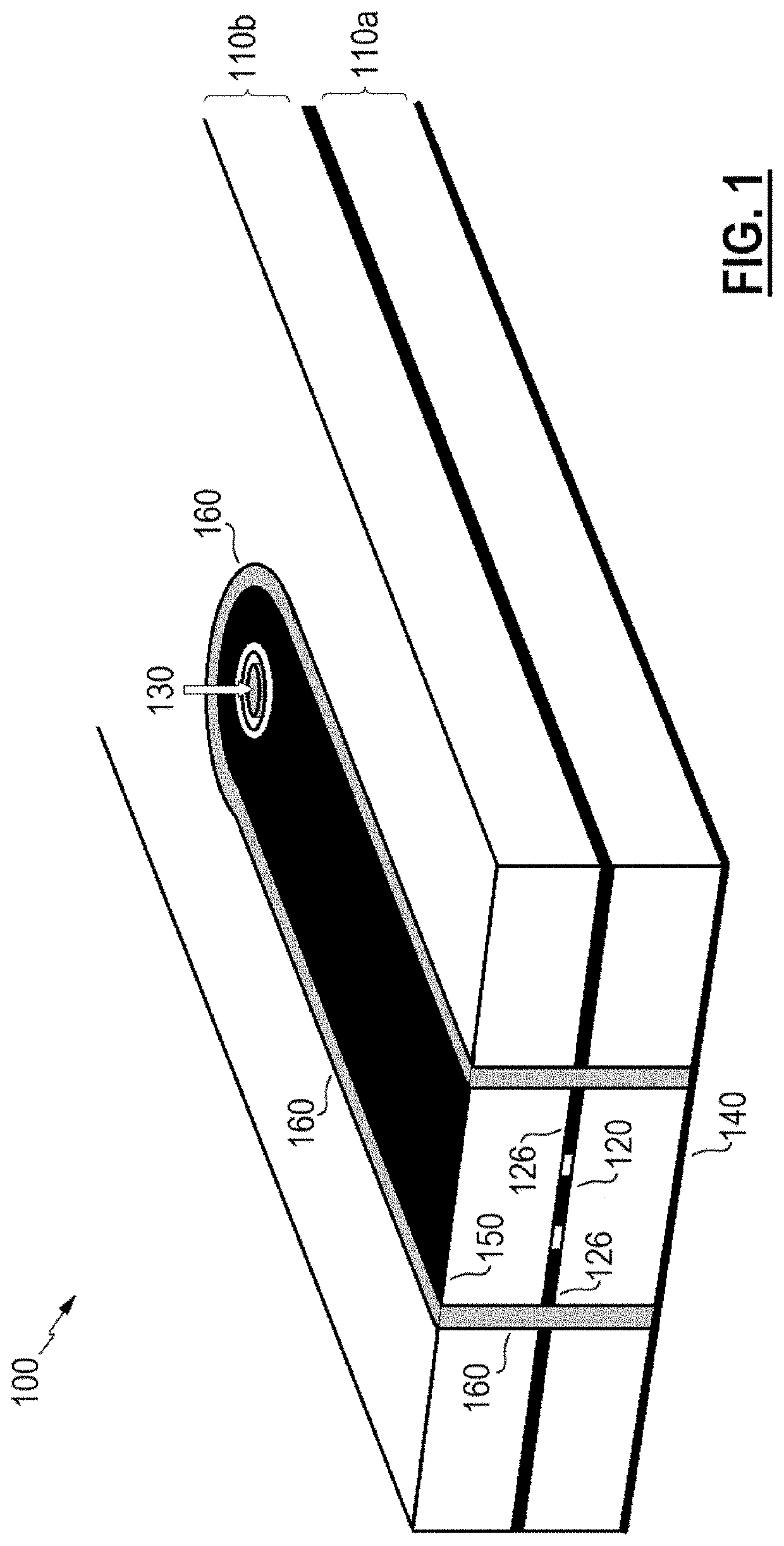
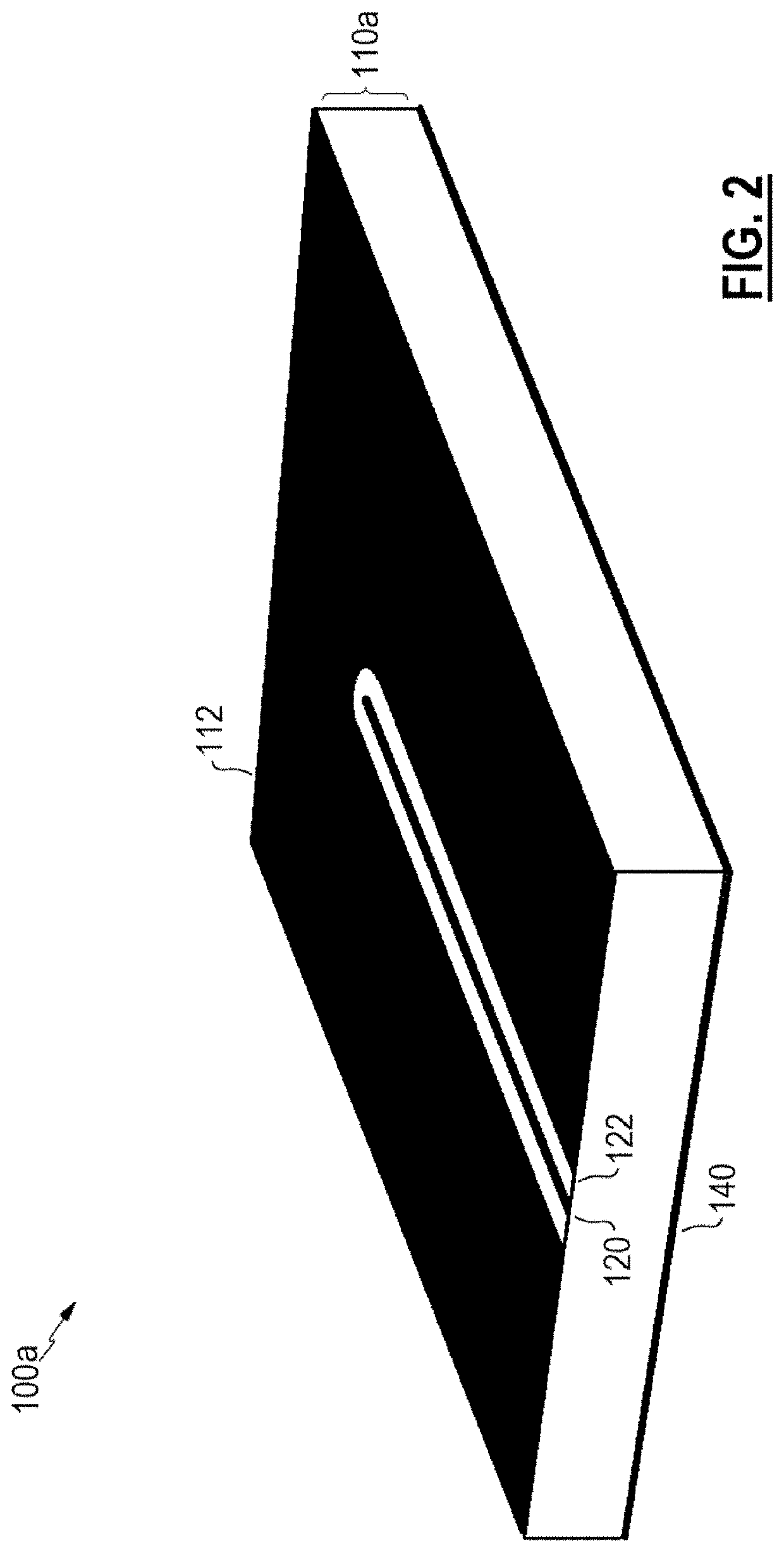
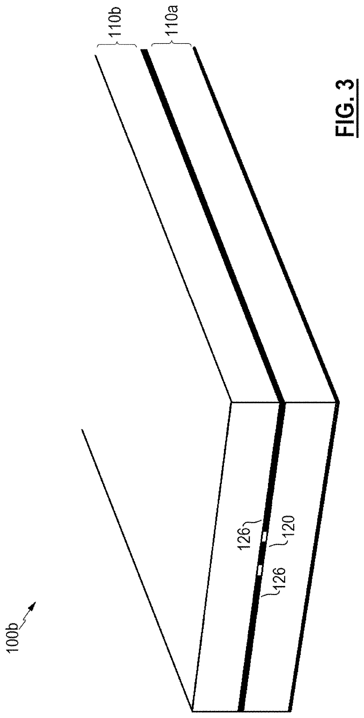
[0019]Aspects and examples described herein provide signal conductors (e.g., transmission lines, signal traces, strip lines) with reference surfaces and conductors within various circuits for the containment and conveyance of millimeter wave signals. The transmission line structures described herein efficiently distribute signal currents while maintaining characteristic impedance and minimizing signal loss along the transmission line. The transmission line structures described herein are suitable for various circuit board manufacturing, including radio frequency circuit embodiments, and advantageously apply subtractive and additive manufacturing techniques. Such techniques may provide structures capable of conveyance and containment of radio frequency signals in microwave and millimeter wave ranges, for example from 28 GHz to 70 GHz, and up to 300 GHz or more.

[0020]Conventional transmission line architectures rely heavily on a center conductor, producing a significant concentration ...


PUM

PropertyMeasurementUnit
insertion lossaaaaaaaaaa
frequencyaaaaaaaaaa
frequencyaaaaaaaaaa

Abstract

Circuits and methods include transmission lines formed from a conductive cladding on a substrate surface. The transmission line includes additional reference conductors positioned co-planar on the surface, including a gap between the transmission line and each of the reference conductors. The transmission line and the reference conductors are at least partially encapsulated (e.g., sandwiched) between two substrates. Isolation boundaries may be included as ground planes, e.g., above and below the transmission line, on opposing surfaces of the substrates, and Faraday walls, e.g., vertically, through the substrates. Current densities generated by various electromagnetic signals are distributed among the transmission line and the reference conductors (as a tri-conductor arrangement), and may be partially further distributed to the isolation (ground) boundaries.

Description

CROSS-REFERENCE TO RELATED APPLICATIONS[0001]This application claims the benefit under 35 U.S.C. § 119(e) of U.S. Provisional Patent Application No. 62 / 691,810 titled MILLIMETER WAVE TRANSMISSION LINE ARCHITECTURE filed on Jun. 29, 2018, U.S. Provisional Patent Application No. 62 / 584,260 titled SPIRAL ANTENNA AND RELATED FABRICATION TECHNIQUES filed on Nov. 10, 2017, U.S. Provisional Patent Application No. 62 / 584,264 titled ADDITIVE MANUFACTURING TECHNOLOGY (AMT) LOW PROFILE RADIATOR filed on Nov. 10, 2017, U.S. Provisional Patent Application No. 62 / 584,300 titled LOW PROFILE PHASED ARRAY filed on Nov. 10, 2017, U.S. Provisional Patent Application No. 62 / 636,364 titled SNAP-RF INTERCONNECTIONS filed on Feb. 28, 2018, and U.S. Provisional Patent Application No. 62 / 636,375 titled ADDITIVE MANUFACTURING TECHNOLOGY (AMT) LOW PROFILE SIGNAL DIVIDER filed on Feb. 28, 2018, each of which is herein incorporated by reference in its entirety for all purposes.BACKGROUND[0002]Radio frequency (R...

Claims


Application Information

Patent Timeline
Patent Type & Authority Patents(United States)
IPC IPC(8): H01P3/00H01P11/00H05K1/02H01P3/08H05K1/11H05K3/28H05K3/00H05K3/04H05K3/10
CPCH01P3/085H05K3/28H01P3/08H05K1/115H01P3/082H01P3/006H05K1/0224H05K3/04H05K3/107H05K3/0044H01P11/003H05K1/0219H05K2201/09854H05K2201/093
Inventor SIKINA, THOMAS V.HAVEN, JOHN P.BENEDICT, JAMES E.
Owner RAYTHEON CO
Why Eureka
Try Eureka