Burn saver device

a technology of burn-saving device and burner, which is applied in the direction of heat measurement, instruments, optical radiation measurement, etc., can solve the problems of difficult for them to know if the external environment has become dangerous, the response time of these devices is too slow to be useful, and the danger of class iv fires is extremely dangerous, etc., to achieve the effect of small effective surface area, and large effective surface area

Active Publication Date: 2020-12-29
TDA RES
View PDF9 Cites 0 Cited by
  • Summary
  • Abstract
  • Description
  • Claims
  • Application Information

AI Technical Summary

Benefits of technology

[0070]In a preferred embodiment the various sensors of the burn saver device of the present invention in its various configurations all have the same surface area. Instead of using two sensors facing in the same direction, but each having two different surface areas, the preferred embodiment of the present invention uses two or more sensors with the same surface area, but facing in different directions; thus, when the radiant heat is emanating from a source there will be at least one sensor facing more directly to the radiant heat source and one facing “off-angle”. The off-angle sensor will have a smaller effective surface area (for radiation absorption). This feature, having at least one sensor with a larger effective surface area and at least one sensor with a smaller effective surface area is illustrated in the various views of FIG. 39, FIG. 40 and FIG. 41. The convective heat measurement (ambient temperature) is not dependent on sensors' directional orientation, but the radiant heat measurement is directly proportional to the effective surface area and thus is directly dependent on the sensors' directional orientation. Using five sensors arranged in the directions of a Catesian coordinate system provides the best coverage of detecting both radiation and convection from any potential direction.

Problems solved by technology

Often, it is the face piece of the Self Contained Breathing Apparatus (SCBA) that is the first component to fail in a high temperature environment, which can lead to catastrophic accidents (FIG. 1.
Class IV fires are extremely dangerous and represent conditions that can be lethal.
Because flashovers are practically impossible to predict with any significant lead time, immediate withdrawal is required when Class IV conditions are detected.
A general problem is that modern PPE is so effective at protecting firefighters that it is difficult for them to know if the external environment has become dangerous until it may be too late.
Unfortunately, the response time of these devices is too slow to be useful (in some cases tens of minutes) since temperatures and radiant heat fluxes can change in a matter of seconds.
Convective heat transfer is important because it can cause failure in the firefighter's PPE.
The most dangerous source of heat in a fire is infrared (IR) radiation and the greatest amount of its energy comes from flame emission.
As with the RTD, the thermistor requires a very stable constant current source, and because semiconductors are used, these devices are usually limited to operating temperatures around 100° C.
The disadvantages are that they not mechanically robust, cannot tolerate high temperatures (like thermistors), require complex signal processing electronics and are relatively expensive.
It is difficult to simultaneously measure the IR flux and ambient air temperature.
Measuring the IR flux and ambient air temperature independently is more difficult than it first appears to be simply for the reasons that thermocouples, thermistors and RTDs are all heated by infrared radiation and heated or cooled by convection depending on the temperatures of the air and temperature sensing device.
The dirty environment or a fire causes problems on devices that rely on clean metal surfaces.
This approach suffers from the limitation that it is not suitable for applications where the firefighter has to wear the device because of the weight, complexity and mechanical unreliability of having to have a pump or heavy fan to generate air velocities upwards of 100 m / s.
These references contain at least one of the following limitations in regard to a portable burn warning device: inability to accurately measure (simultaneously) infrared radiation and convective heat, inability to work in the dirty fire environment, excessive weight, complexity, or mechanical unreliability.
Fire environment makes using low emissivity thermocouple coatings impossible.

Method used


Image

  • Burn saver device
  • Burn saver device
  • Burn saver device

Examples


example 1

ing Apparatus

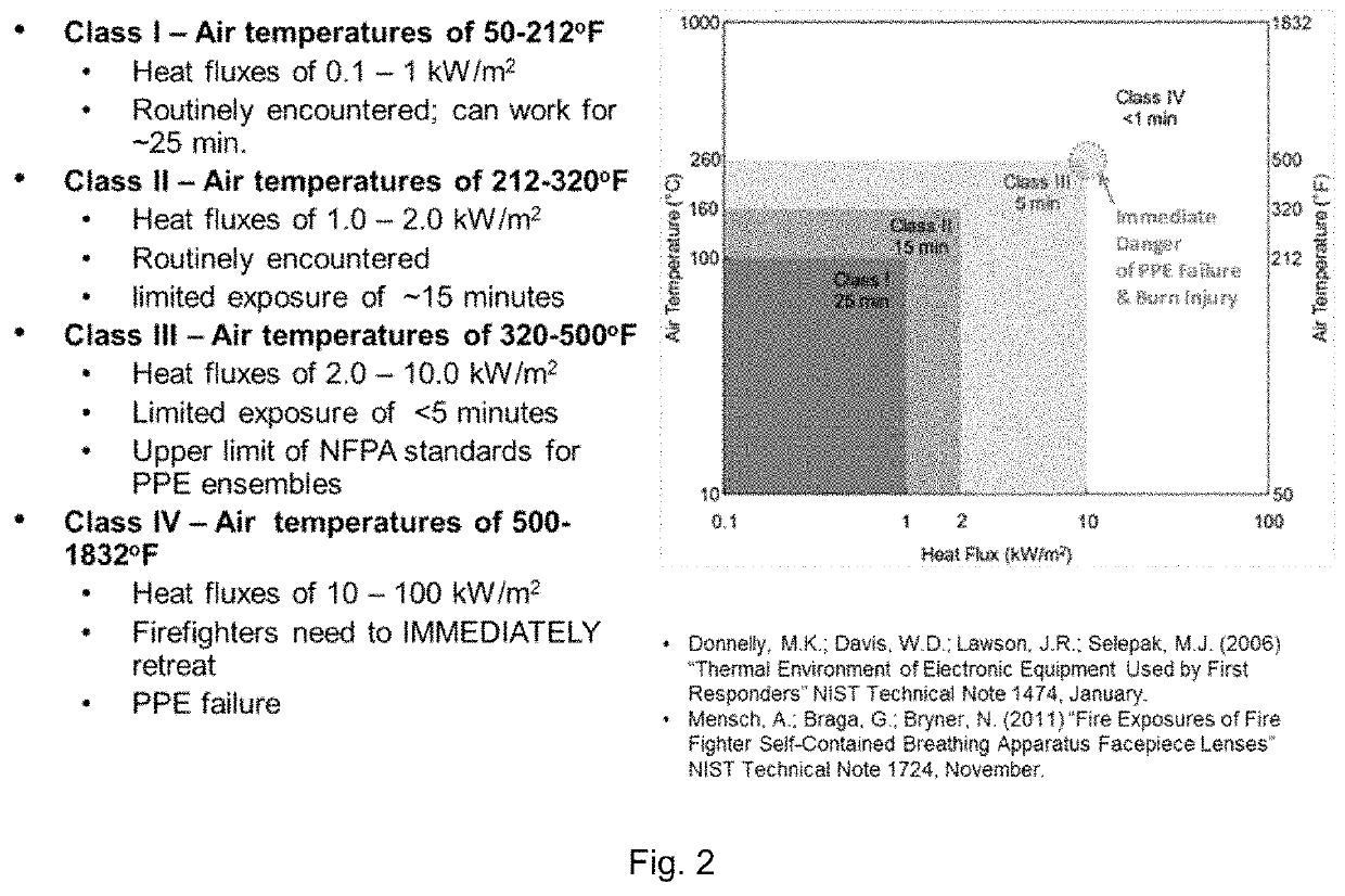
[0172]An apparatus for testing the Burn Saver device was constructed and calibrated to operate in free and forced convection, and in radiation heat transfer modes (FIG. 25). The heat transfer modes match key set points derived from research efforts by Mensch et al. 2011 and Donnelly et al. 2006 that describe the heat fluxes and air temperatures used to classify fires into four hazard types (FIG. 14).

[0173]The apparatus acts like a convection oven that has been designed so that both convective and radiative heat loads can be varied simultaneously and independently. Calibration of the unit was done to characterize the output of the radiant heater at stepped power input levels.

[0174]The radiant power level was obtained by using the IR source to heat a round aluminum billet that had been coated with acetylene black (ε=0.97). The calorimeter was in direct line of sight with the IR source. The heat flux can be determined by measuring the temperature rise of the metal billet a...

example 2

e of a Burn Saver Device with One Square and One Rectangular Sensing Element

[0178]In this example two front facing foils of different size are used to simultaneously measure radiant heat flux and ambient temperature (FIG. 29). The large foil 901 is 0.25 inches by 0.75 inches and the small foil 902 is 0.25 inches by 0.25 inches. Both foils are heated radiantly and convectively, but they have different convective heat transfer coefficients because of their different sizes, which permits calculating the ambient temperature. This example also uses an optional flow straightening device 904 attached to the front of the Burn Saver that increases the convective heat transfer coefficients substantially by increasing the amount of flow that directly impinges onto the foils. This modification does not block any IR and protrudes 0.25″. Thermocouple wires 903 are attached to the foil.

[0179]The IR sensor foils were coated with a high temperature, high emissivity, flat-black spray paint (Rustoleum...

example 3

Burn Saver Device: Two Sizes of Detector Foils are Used in the Front Sensor

[0181]The temperature vs. time data from the two foils is used to calculate the heat flux (equation 12) and ambient temperature (equation 18).

[0182]Calculating the radiative heat flux is done using the data from the front, top and back thin foil sensors (FIG. 33). Alternative designs are possible with more or fewer sensors in different direction. IR is directional because it is electromagnetic radiation. The heat flux (kW / m2) is calculated (equation 12) the same way that we calibrated our IR source with the calorimeter except that our thermal masses (the foils) are much smaller than the mass of the blackened aluminum billet. In FIG. 32 the sensor foil heats up to steady state in about 6 seconds after the 10 kW / / m2 IR source is switched on, which gives a heating rate of 26° C. / sec. The slope of the temperature vs. time curve is used to calculate the radiant heat flux using Equation 12.

[0183]Equation 12. Radian...


PUM

PropertyMeasurementUnit
Biot numberaaaaaaaaaa
thickaaaaaaaaaa
thickaaaaaaaaaa

Abstract

A decoupling radiant and convective heat sensing device having sensor elements facing in different directions, and a decoupling radiant and convective heat sensing device having sensor elements facing in different directions with a means for determining the remaining time before a Self Contained Breathing Apparatus facemask will become compromised by dangerous heat conditions.

Description

CROSS REFERENCE TO RELATED APPLICATIONS[0001]The present application claims the benefit of the provisional application No. 61 / 895,322 filed Oct. 24, 2013 (titled BURN SAVER DEVICE, by Girish Srinivas, Michael Karpuk, Steven Gebhard and Joe Fredrickson), which is incorporated by reference herein. The present invention also claims the benefit of non-provisional application Ser. No. 14 / 523,516 filed Oct. 24, 2014 (titled BURN SAVER DEVICE by Girish Srinivas, Michael Karpuk, Steven Gebhard and Joe Fredrickson), which is incorporated by reference herein.) Provisional application No. 61 / 895,322 and non-provisional application Ser. No. 14 / 523,516 are not admitted to be prior art with respect to the present invention by its mention in the background or cross-reference section.STATEMENT REGARDING FEDERALLY SPONSORED RESEARCH OR DEVELOPMENT[0002]This invention was made using U.S. government funding through the U.S. Department of Homeland Security contract HSHQDC-13-C-00042. The government has...

Claims


Application Information

Patent Timeline
Patent Type & Authority Patents(United States)
IPC IPC(8): G01J5/00G01K17/00G01K7/02G01J5/04G01J5/08G01J5/02G01J5/12A62B9/00G01K7/42
CPCG01K7/02G01J5/04G01J5/0018G01J5/0265G01J5/12G01J5/0853A62B9/006G01K17/00G01J5/025G01K7/427G01J5/0215
Inventor SRINIVAS, GIRISHKARPUK, MICHAELGEBHARD, STEVENFREDRICKSON, JOEGALLOWAY, ANDREW D.
Owner TDA RES
Why Eureka
Try Eureka