

Moldable silicon nitride green-body composite and reduced density silicon nitride ceramic process
a technology of green-body composite and silicon nitride, which is applied in the field of moldable silicon nitride green-body composite and reduced density silicon nitride ceramic process, can solve the problems of undesirable reaction layer formation, difficult control and expensive process, and inability to achieve the desired dielectric properties, and achieve easy flow into molds, promote reaction and cross-linking, and enhance particle dispersion
Active Publication Date: 2021-04-06
ATC MATERIALS INC
View PDF27 Cites 1 Cited by
- Summary
- Abstract
- Description
- Claims
- Application Information
AI Technical Summary
Benefits of technology
The invention is about a new material that can be molded and then converted to a high-strength ceramic. The material is made up of silicon nitride and a binder. The process involves heating the material to a high temperature and converting the binder to silicon nitride. This conversion process ensures that the material has uniform properties and minimal shrinkage. The resulting ceramic part has a smooth surface and can be easily machined. The material can also be ground to a small size for easy molding. The ceramic part has low dielectric constant and low loss properties, making it useful in applications such as electrical components. The process also allows for the inclusion of other materials to improve the properties of the ceramic part.
Problems solved by technology
Because of this, the dielectric properties are not as desirable as could be.
While this process yields parts with good dielectric properties, the process is difficult to control and expensive.
This is due to the fact that tolerances, typically, cannot be held in these processes and, in addition, an undesirable reaction layer is formed on the surface of the parts which needs to be removed post sinter.
Ceramics, including silicon nitride, are difficult to machine as they are very hard and as a result material removal rates are very slow.
The cost of post surfacing the sintered molded part can easily exceed any of the prior manufacturing cost.
The amount of effort to achieve this, however, is not feasible from a practical standpoint.
For parts with large cross-sections, even 10 vol. percent represents a difficult de-binding (burnout) challenge.
In addition to the difficulties that a large amount of binder presents during processing, the large amount of binder can negatively impact the strength and density of the sintered part and it also can act as a contaminate that degrades the dielectric properties.
During densification or sintering, ceramics, including silicon nitride parts, shrink substantially during the sintering process making it difficult to maintain important dimensional aspects that can be critical for an application.
Method used
View moreImage
Smart ImageViewing Examples

Examples
example
[0044]An exemplary moldable green-body composite was made according to the present invention with the composition as described in Table 1. The concentration of the silicon nitride was about 82% by weight. The concentration of the binder was about 15% by weight and the concentration of surface modifier, methyltriethoxysilane. (MTES) of about 1% by weight. Anti-agglomeration agent, stearic acid is included in a concentration of about 0.18% by weight. The sintering aids are include in a combined concentration of about 2% by weight.
[0045]
TABLE 1Mass% ofComponent(g)TotalSi3N430082Al2O33.10.88Y2O34.31.18Binder5414.77MTES30.82Stearic acid1.20.33
Login to View More PUM
| Property | Measurement | Unit |
|---|---|---|
| Temperature | aaaaa | aaaaa |
| Percent by mass | aaaaa | aaaaa |
| Percent by mass | aaaaa | aaaaa |
Abstract
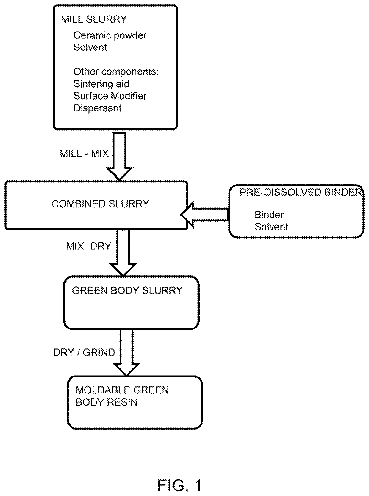
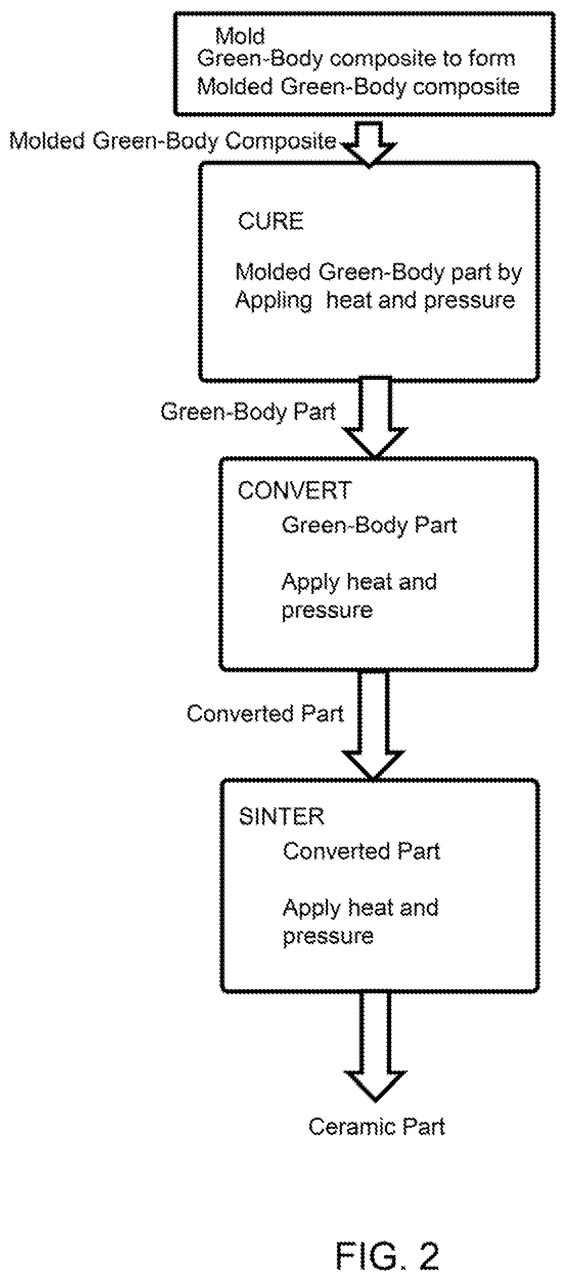
A moldable green-body composite includes milling silicon nitride powder with a solvent and adding a surface modifier to the milled slurry to modify a surface of the silicon nitride particles. A polysiloxane in a solvent and a binder are also added to create a green body slurry. The solvents may be polar or non-polar solvents. A sintering aid, such as yttria-alumina, may be added to the slurry as well. A reduced density silicon nitride ceramic is made from the moldable green-body composite by molding the moldable green-body composite in a mold and curing at a curing temperature to convert the moldable green-body composite to a converted composite. The converted composite can then be sintered to form a reduced density silicon nitride ceramic that has a smooth surface finish and requires no post machining or polishing. The reduced density silicon nitride ceramic may also have very good dielectric properties.
Description
CROSS REFERENCE TO RELATED APPLICATIONS[0001]This application claims the benefit of priority to U.S. provisional patent application No. 62 / 533,771, filed on Jul. 18, 2017; the entirety of which is hereby incorporated by reference herein.BACKGROUND OF THE INVENTIONBackground[0002]Silicon nitride is a ceramic with, among other things, interesting microstructural characteristics, desirable electrical properties for radio frequency (RF) applications (i.e., radomes, windows and conformal antenna parts) and high temperature capability. While silicon nitride is most commonly used in the structural ceramic market as bearings and other structural parts, it has long been considered a desirable material for elevated temperature RF applications. This is due to its strength at high temperature and potential for very good dielectric properties.[0003]Today there are two common routes to forming bulk silicon nitride parts. The first is by sintering silicon nitride powder, with or without applied pr...
Claims
Login to View More Application Information
Patent Timeline
 IPC IPC(8): C04B35/584C04B35/634C04B35/626C04B35/645
CPCC04B35/584C04B35/6261C04B35/6264C04B35/63448C04B35/645C04B2235/402C04B2235/428C04B2235/602C04B2235/608C04B2235/612C04B2235/6567C04B2235/6582C04B2235/483C04B2235/3873C04B2235/5436C04B35/62685C04B35/62655C04B35/62802C04B35/632C04B2235/3225C04B2235/3217C04B2235/3222C04B2235/3205C04B2235/3206C04B2235/3227C04B35/638C04B2235/6587C04B2235/6022C04B2235/9615C04B2235/658C04B2235/945
InventorHAWTHORNE, MARK
OwnerATC MATERIALS INC