
Method for ironmaking by smelting reduction in stir-generated vortex

a technology of stir-generated vortex and smelting reduction, which is applied in the direction of melt circulation arrangement, electric/magnetic/electromagnetic heating, metal processing, etc., can solve the problems of low utilization rate of pulverized coal, waste of raw materials, and small profit margin, and achieve rapid reduction of iron-containing oxides and low utilization ra

Active Publication Date: 2021-08-17
NORTHEASTERN UNIV
View PDF20 Cites 0 Cited by
  • Summary
  • Abstract
  • Description
  • Claims
  • Application Information

AI Technical Summary

Benefits of technology

This patent describes a new way to make iron in a blast furnace. The method involves using an induction furnace with a stirring paddle to create a vortex. In this method, the raw materials, reducing agent, and slag-forming agent are added to the center of the vortex and are quickly drawn into the smelting pool. This allows for full contact between the materials and faster reaction times, reducing the ironmaking process. The method is simple, energy-efficient, and cost-effective, and it has high economic value. Additionally, the utilization rate of the reducing agent is greatly increased, making it an efficient non-blast-furnace iron-making technology.

Problems solved by technology

As the mature blast-furnace ironmaking process has made ironmaking cost to be stable, improvements on local conditions can only change pig iron cost to a small extent, producing a small profit margin.
The low density of pulverized coal enables a large amount of pulverized coal to float on the surface in the reaction process, so that the pulverized coal cannot react well with iron oxides and the utilization rate of the pulverized coal is low; and a lot of unreacted dust exists in produced flue gas, so that raw materials are wasted, and atmosphere and environment on site can also be badly influenced.

Method used


Image

  • Method for ironmaking by smelting reduction in stir-generated vortex

Examples


embodiment 1

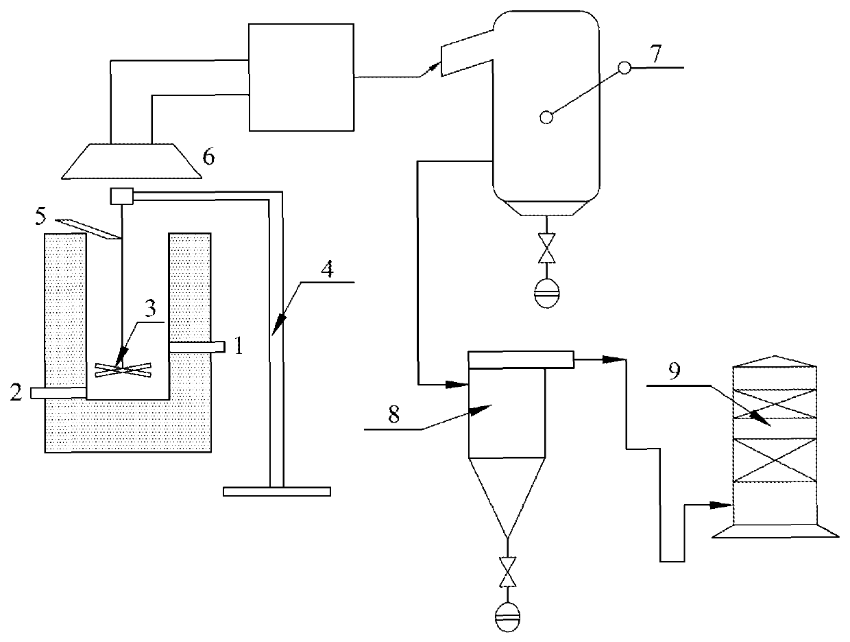
[0037]The structural diagram of the induction furnace system of the embodiment refers to the sole FIGURE.

[0038]The method for ironmaking by smelting reduction in a stir-generated vortex comprises the following steps:

[0039](1) Placing a pig iron in an induction furnace, heating the pig iron to a molten state to form a molten iron, and maintaining a temperature of the molten iron to be greater than or equal to 1,450° C. for providing heating environment, wherein an amount of the pig iron is 5 vol % of an induction furnace body;

[0040](2) Inserting a graphite stirring paddle 3 to ⅓ of a liquid level of the molten iron for a center stirring at a stirring speed of 50 r / min, so that a vortex with a height-to-diameter ratio of 0.5 is formed, and the stirring is continued;

[0041]Replacing the stirring paddle 3 through a stirring paddle lifting system 4 according to a degree of wear of the graphite stirring paddle 3, and smashing the worn graphite stirring paddle 3 for reuse as a reducing agen...

embodiment 2

[0044]The structural diagram of the induction furnace system of the embodiment refers to the sole FIGURE.

[0045]The method for ironmaking by smelting reduction in a stir-generated vortex comprises the following steps:

[0046](1) Placing a pig iron in an induction furnace, heating the pig iron to a molten state to form a molten iron, and maintaining a temperature of the molten iron to be greater than or equal to 1,550° C. for providing heating environment, wherein an amount of the pig iron is 15 vol % of an induction furnace body;

[0047](2) Inserting a graphite stirring paddle 3 to ½ of a liquid level of the molten iron for a center stirring at a stirring speed of 200 r / min, so that a vortex with a height-to-diameter ratio of 2.5 is formed, and the stirring is continued;

[0048]Replacing the stirring paddle 3 through a stirring paddle lifting system 4 according to a degree of wear of the graphite stirring paddle 3;

[0049](3) Performing mixing and grinding on an iron ore, a pulverized coal a...

embodiment 3

[0051]The structural diagram of the induction furnace system of the embodiment refers to the sole FIGURE.

[0052]The method for ironmaking by smelting reduction in a stir-generated vortex comprises the following steps:

[0053](1) Placing a pig iron in an induction furnace, heating the pig iron to a molten state to form a molten iron, and maintaining a temperature of the molten iron to be greater than or equal to 1,500° C. for providing heating environment, wherein an amount of the pig iron is 20 vol % of an induction furnace body;

[0054](2) Inserting a graphite stirring paddle 3 to ½ of a liquid level of the molten iron for a center stirring at a stirring speed of 100 r / min, so that a vortex with a height-to-diameter ratio of 1.0 is formed, and the stirring is continued;

[0055]Replacing the stirring paddle 3 through a stirring paddle lifting system 4 according to a degree of wear of the graphite stirring paddle 3;

[0056](3) Performing mixing and grinding on an iron ore, a pulverized coal a...


PUM

PropertyMeasurementUnit
temperatureaaaaaaaaaa

Abstract

A method for ironmaking by smelting reduction in a stir-generated vortex includes: (1) placing a pig iron in an induction furnace, and then heating the pig iron to a molten state to form a molten iron, and maintaining the molten iron to be greater than or equal to 1450° C.; (2) stirring a center of the molten iron to form a vortex with a height-to-diameter ratio of 0.5-2.5, and continuously performing stirring; (3) mixing and grinding on an iron-containing mineral, a reducing agent and a slag-forming agent in a mass ratio of 1:(0.1-0.15):(0.25-0.4) to obtain a powder mixture, spraying and blowing the powder mixture to a center of the vortex, performing a reduction reaction, and stopping the stirring after the molten iron and molten slags are obtained, wherein a waste gas is produced; and (4) discharging the molten iron and the molten slags respectively, and exhausting a treated waste gas.

Description

BACKGROUND OF THE INVENTION1. Field of the Invention[0001]The present invention belongs to the field of metallurgical technology, and particularly relates to a method for ironmaking by smelting reduction in a stir-generated vortex.2. The Prior Arts[0002]China's steel industry has grown rapidly over years of high-speed development, accounting for 40% or above of global steel production capacity. However, reducing cost and improving working environment have become top priorities in the face of steel overcapacity and increasingly-strict environmental requirements. As the basis of steelmaking, an ironmaking process is perfect. In China, ironmaking mainly refers to blast-furnace ironmaking. The blast-furnace ironmaking is mainly a reduction process of iron, that is, iron in ore for ironmaking is reduced from oxides to molten pig iron at high temperatures by using coke as fuel and reducing agents.[0003]Under harsh economic situations, ironworks take various measures to continue reducing p...

Claims


Application Information

Patent Timeline
Patent Type & Authority Patents(United States)
IPC IPC(8): C21B11/10H05B6/06H05B6/36H05B6/34C21C1/04
CPCC21B11/10C21C1/04H05B6/067H05B6/34H05B6/367C21B2300/02Y02P10/25
Inventor ZHANG, TING ANLIU, YANDOU, ZHI HEZHANG, ZI MULV, GUO ZHI
Owner NORTHEASTERN UNIV
Learn More