
Arrangement for filtering out damaging heat created from laser energy contacting a kidney stone

a technology of laser energy and filtering, which is applied in the field of filtering out damaging heat created by laser energy contacting kidney stones, can solve the problems of fiber becoming very weak and easily breaking when bent, and achieve the effect of preventing carbonization of cladding, coating or buffer layer

Active Publication Date: 2022-02-22
OPTICAL INTEGRITY INC
View PDF10 Cites 0 Cited by
  • Summary
  • Abstract
  • Description
  • Claims
  • Application Information

AI Technical Summary

Benefits of technology

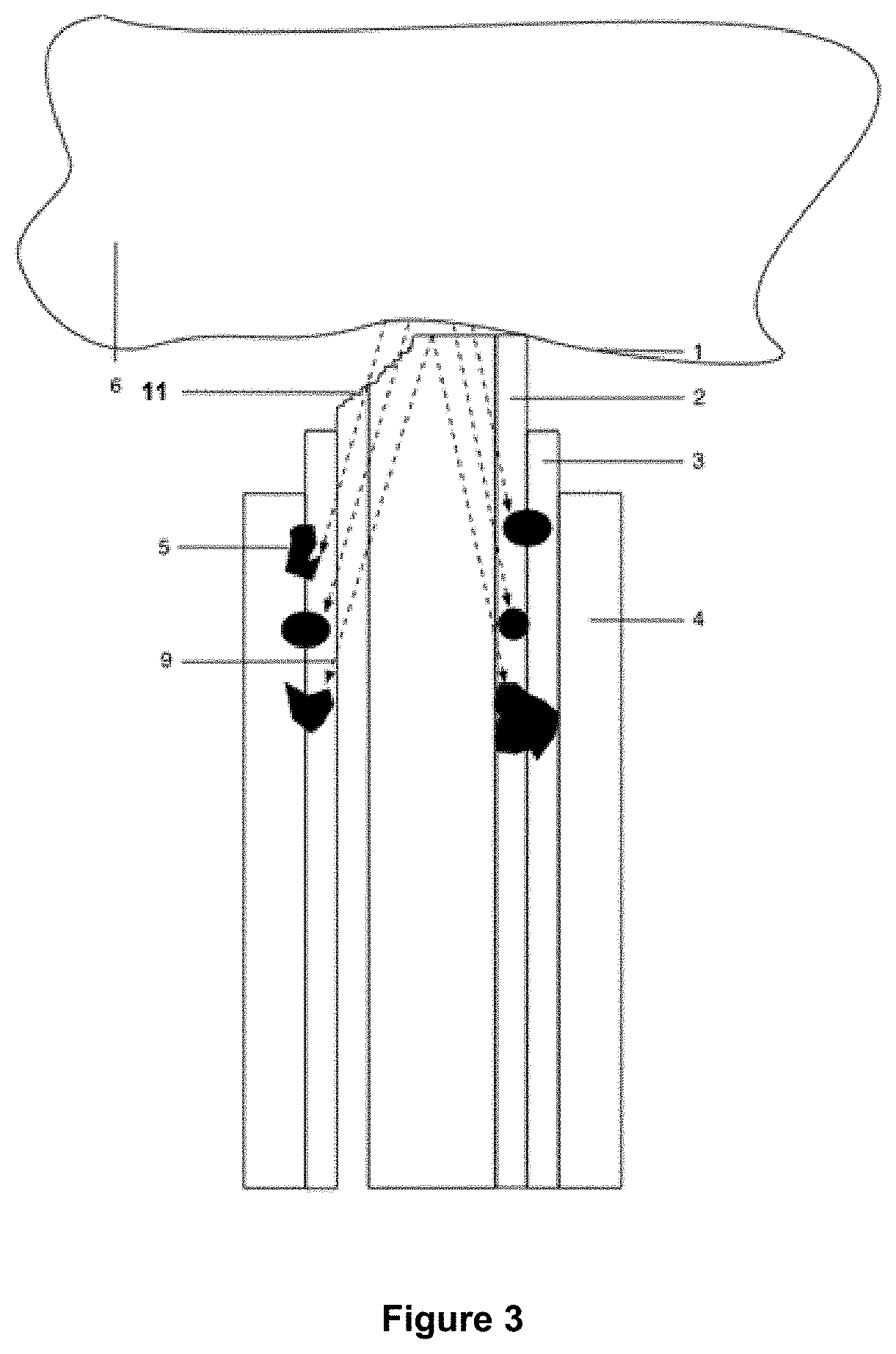
The objective of this patent is to prevent the laser fiber from getting burned and charred when it targets a kidney stone or other target. The patent proposes an arrangement that protects the cladding, coating, or buffer layers of the fiber from this thermal radiation. The distal end of the fiber may be protected by a standoff or a fiber tip protective structure that can prevent further erosion and lower the density of power applied to the target.

Problems solved by technology

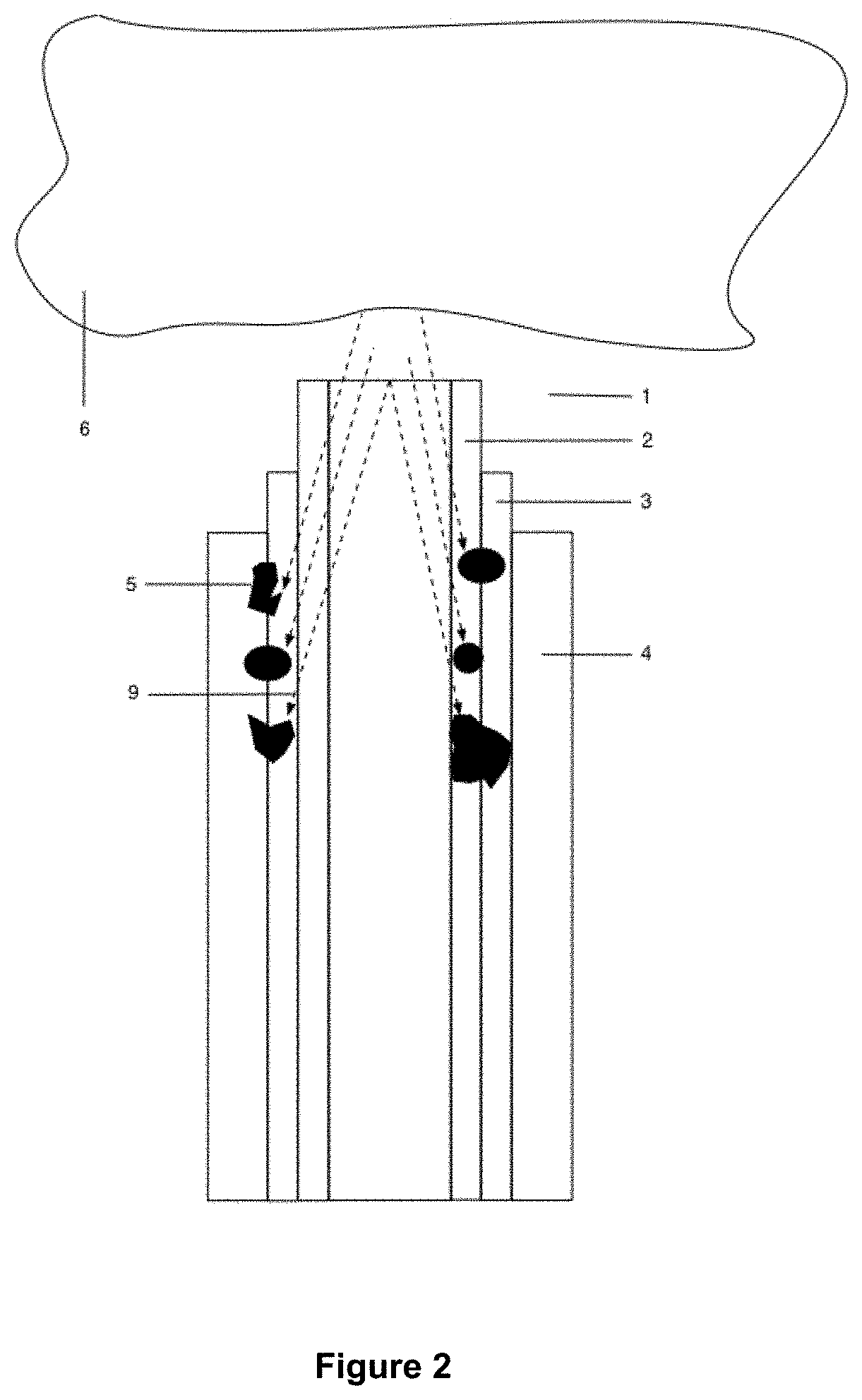
When a carbonization zone 5 touches the silica cladding layer 2, the fiber becomes very weak and can easily break when bent.

Method used


Image

  • Arrangement for filtering out damaging heat created from laser energy contacting a kidney stone
  • Arrangement for filtering out damaging heat created from laser energy contacting a kidney stone
  • Arrangement for filtering out damaging heat created from laser energy contacting a kidney stone

Examples


Embodiment Construction

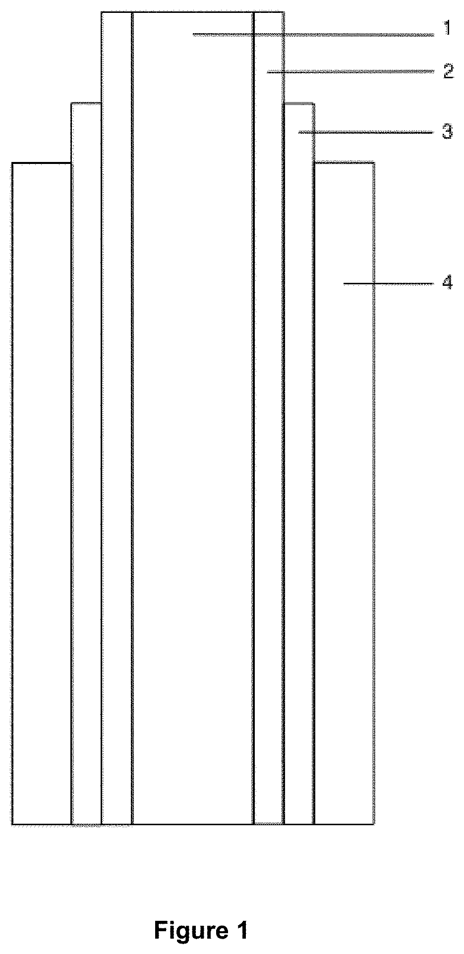
[0025]FIG. 5 shows a carbonization preventing arrangement according to a first preferred embodiment of the invention. The carbonization preventing arrangement is applied, for illustrative purposes, to a surgical laser fiber such as the one shown in FIG. 1, which includes a fused silica core 1, a fluorine doped fused silica cladding layer 2, a hard polymer coating layer 3, and an ethylene tetrafluoroethylene (ETFE) buffer layer 4. The materials and configuration of the core and fiber layers are exemplary and may be varied without departing from the scope of the present invention. In addition, the illustrations of the fiber are schematic in nature, and not intended to provide an indication of scale.

[0026]The carbonization preventing arrangement of FIG. 5 is implemented by replacing a section of the coating layer 4 and buffer layer 5 with a thermal radiation blocking, absorbing and / or redirecting structure 15 that extends towards the distal end of the fiber, and that prevents damage to...


PUM

PropertyMeasurementUnit
heat resistantaaaaaaaaaa
heat conductiveaaaaaaaaaa
thermalaaaaaaaaaa

Abstract

An arrangement that prevents carbonization of cladding, coating, or buffer layers of a surgical laser fiber due to thermal radiation reflected back into the fiber from, or emitted by, a target of the laser, includes a thermal radiation blocking, absorbing or diverting structure. The thermal radiation blocking, absorbing or diverting structure surrounds an end portion of the fiber that has been stripped of one or more coating and / or buffer layers, and may be made of a heat resistant material such as PTFE or polyimide to block heat from reaching the coating or buffer layers, an optical ferrule such as fused silica to guide the heat away from the fiber coating or buffer layers, or a high refraction index material such as UV adhesive.

Description

[0001]This application claims the benefit of U.S. Provisional Patent Appl. Ser. No. 62 / 720,365, filed Aug. 21, 2019.BACKGROUND OF THE INVENTION1. Field of the Invention[0002]The invention relates to an arrangement for preventing damage to an optical fiber caused by thermal radiation reflected back into the fiber from a surgical laser target such as a kidney stone.[0003]More particularly, the invention provides a structure that prevents reflected thermal radiation from carbonizing layers of the fiber by blocking, absorbing and / or diverting the reflected thermal radiation. The carbonization preventing structure surrounds the fiber core and cladding at the distal end of the fiber, replacing coating and / or buffer layers that have been stripped from the fiber, to form a filter for the reflected thermal radiation.[0004]The carbonization preventing structure may advantageously be combined with a surrounding standoff or protective tip structure that establishes a minimum spacing between the...

Claims


Application Information

Patent Timeline
Patent Type & Authority Patents(United States)
IPC IPC(8): A61B18/20A61B18/24A61B18/26A61B18/22
CPCA61B18/245A61B18/26A61B2018/2015A61B2018/2244A61B2018/00511
Inventor BROWN, JOE DENTONMALPHURS, DANIEL
Owner OPTICAL INTEGRITY INC
Learn More