Ceramics and their powder for scintillators, and method for producing same

a technology of scintillator and powder, which is applied in the direction of inorganic chemistry, crystal growth process, spectral modifier, etc., can solve the problems inability to easily work, and high toxic ions, and achieves small attenuation time constant and afterglow. , the effect of high luminescence intensity

Inactive Publication Date: 2002-01-31
HITACHI METALS LTD
View PDF0 Cites 16 Cited by
  • Summary
  • Abstract
  • Description
  • Claims
  • Application Information

AI Technical Summary

Benefits of technology

0006] Accordingly, an object of the present invention is to provide an inexpensive, oxide-type ceramic and its powder for a scintillator capable of providing high luminescence intensity with small attenuation time constant and afterglow.

Problems solved by technology

Among these scintillators, the single crystal CdWO.sub.4 scintillator is disadvantageous in that it does not provide high luminescence intensity, that it cannot easily be worked because of cleavage, and that it contains a highly toxic ion of Cd.
Though Gd.sub.2O.sub.2S:Pr,Ce,F has a high luminescence efficiency with small attenuation time constant and afterglow, it is disadvantageous in that it is produced through complicated processes, resulting in high production cost.

Method used


Image

  • Ceramics and their powder for scintillators, and method for producing same
  • Ceramics and their powder for scintillators, and method for producing same
  • Ceramics and their powder for scintillators, and method for producing same

Examples


example 1

Comparative Examples 1-3

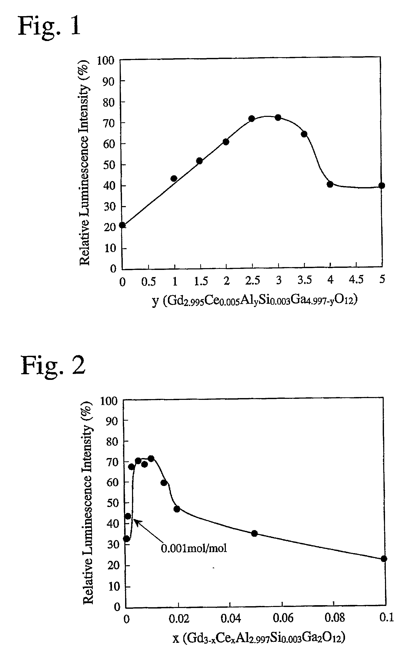
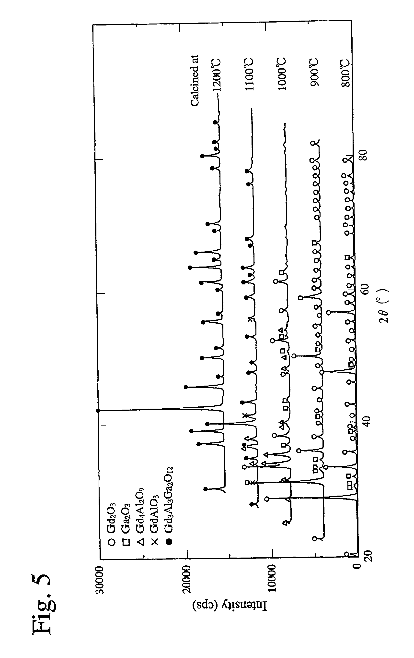
[0035] 135.48 g of Gd.sub.2O.sub.3, 0.883 g of Ce.sub.2(C.sub.2O.sub.4).su-b.3.multidot.9H.sub.2O, 38.16 g of Al.sub.2O.sub.3, 0.31 g of Si(OC.sub.2H.sub.5).sub.4, 50.61 g of Ga.sub.2O.sub.3, and 21.92 g of BaF.sub.2 were wet-mixed by a ball mill and dried. The resultant mixed powder was charged into an alumina crucible of a B5 size with an alumina lid, and calcined at 1500.degree. C. for 2 hours. After cooling, the calcined mixture was disintegrated, washed with 4N-hydrochloric acid for 2 hours with a stirrer, and then with pure water and dried. The mixture was ball-milled for 24 hours together with alumina balls of 5 mm in diameter (purity: 99.9%) in a polyethylene pot to provide pulverized scintillator powder of 0.7 .mu.m in average diameter. This powder was mixed with 5% by weight of pure water and then monoaxially pressed at pressure of 500 kg / cm.sup.2. It was then subjected to cold-isostatic pressing at pressure of 3 tons / cm.sup.2 to provide a green bod...

examples 2-8

Comparative Examples 4-7

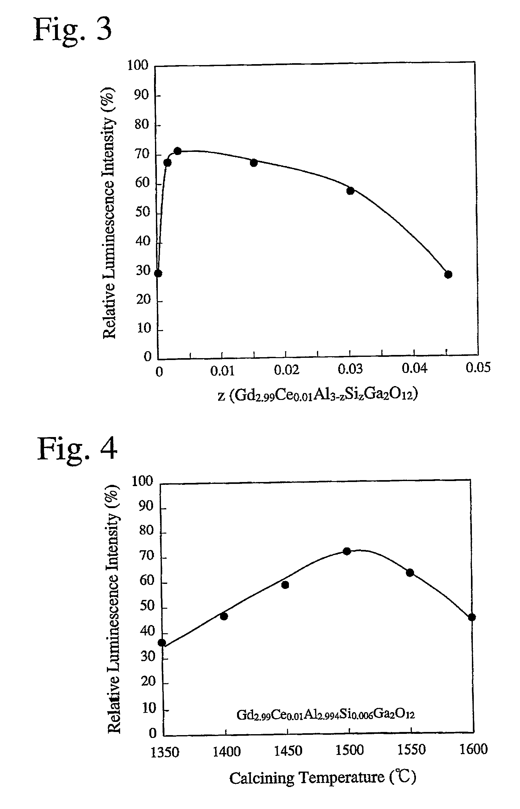
[0043] Sintered bodies having compositions shown in Table 2 were produced in the same manner as in EXAMPLE 1 except for changing the percentages of Al.sub.2O.sub.3, ethyl silicate and Ga.sub.2O.sub.3, the calcining temperature and the sintering temperature. The diffusion transmittance, relative luminescence intensity, attenuation time constant and afterglow of each of the resultant ceramic scintillators are shown in Table 2. Those sintered in vacuum or in an atmosphere at less than 5.times.10.sup.4 Pa suffered from extreme evaporation of Ga, resulting in a relative density of less than 90%.

2TABLE 2 Sintering HIP Diffusion Relative Attenuation Afterglow Temp. Temp. Transmittance Luminescence Time After No. Composition (.degree. C.) (.degree. C.) at 550 nm (%) Intensity (%) Constant (.mu.s) 30 ms (%) EX. 1 Gd.sub.2.99Ce.sub.0.01Al.sub.2.994Si.sub.0.006Ga.sub.2O.sub.12 1700 1500 65 180 <1 0.01 EX. 2 Gd.sub.2.99Ce.sub.0.01Al.sub.0.997Si.sub.0-.003Ga.sub.4O.sub.12...


PUM

PropertyMeasurementUnit
temperatureaaaaaaaaaa
diameteraaaaaaaaaa
temperatureaaaaaaaaaa

Abstract

A sintered ceramic for a scintillator having a composition represented by the general formula of Gd3-xCexAlySizGa5-y-zO12, wherein 0.001<=x<=0.05, 1<=y<=4, and 0.0015<=z<=0.03, is produced by mixing gadolinium oxide, aluminum oxide, gallium oxide, a cerium salt, a silicon compound and a fluorine compound in such proportions as to provide the above composition; calcining the resultant mixture at a temperature of 1400-1600° C.; disintegrating the resultant calcined body to ceramic powder; pressing the ceramic powder to provide a green body; and sintering the green body at a temperature of 1600-1700° C. in a non-oxidizing atmosphere at 5x10⁴ Pa or more, and optionally further by hot isostatic pressing at a temperature of 1400-1600° C. in an argon atmosphere.

Description

[0001] The present invention relates to a ceramic, ceramic powder for scintillators for use in radioactive ray detectors for detecting X-ray, and a method for producing such ceramic and its powder.PRIOR ART[0002] Scintillators are materials emitting visible light upon receiving radioactive rays. Because the intensity of radioactive rays is in a proportional relation to the amount of light emitted from the scintillator, radioactive rays can be measured by a combination of the scintillator and a photodetector. Such technology is utilized mainly in medical apparatuses such as X-ray CTs, analysis apparatuses, non-destructive inspection apparatuses utilizing radioactive rays, apparatuses for detecting leaked radioactive rays, etc.[0003] The scintillators are required to have properties such as high sensitivity to radioactive rays, high material uniformity and chemical stability. Further, when scintillators are used in apparatuses for rapidly detecting the changes of the intensity of radi...

Claims


Application Information

Patent Timeline
Patent Type & Authority Applications(United States)
IPC IPC(8): G01T1/20C01G15/00C04B35/50C09K11/00C09K11/08C09K11/80G01T1/202
CPCC01G15/006C04B35/50C09K11/7774C09K11/77744
Inventor NAKAMURA, RYOUHEI
Owner HITACHI METALS LTD
Why Eureka
Try Eureka