Slurry for chemical mechanical polishing of metal layer, method of preparing the slurry, and metallization method using the slurry

a technology of mechanical polishing and slurry, which is applied in the direction of polishing compositions with abrasives, basic electric elements, electric instruments, etc., can solve the problems of excessive removal of certain material layers or portions thereof, high surface structure complexity of such semiconductor devices, and number of well-known fabrication problems, etc., to improve the reproducibility of the cmp process, improve the reproducibility, and strong oxidizing ability

Inactive Publication Date: 2002-02-14
SAMSUNG ELECTRONICS CO LTD
View PDF0 Cites 52 Cited by
  • Summary
  • Abstract
  • Description
  • Claims
  • Application Information

AI Technical Summary

Benefits of technology

0062] After the preparation of the first and second solutions is completed, and just before CMP, the first solution is diluted with deionized water (step 130). Next, the diluted first solution is mixed at a predetermined ratio with the second solution (step 140), thereby resulting in a CMP slurry according to the present invention.
0063] In one particular embodiment, H.sub.2O.sub.2 and deionized water are added to a commercially available silica abrasive, to prepare the first solution. Fe(NO.sub.3).sub.3 is added to and dissolved in citric acid, and deionized water, EDTA-diammonium salt hydrate and HF are added in succession to the resulting solution, so that the second solution is prepared. As needed, H.sub.2SO.sub.4 may be added to adjust the pH of the second solution. 20 l of slurry including an abrasive of 5% by weight based on the total weight of the slurry can then be prepared as follows. In the case where the first solution includes 25% by weight abrasive, 4 l of the first solution is diluted with 15 l of deionized water, so that 19 l of first solution with 5% by weight abrasive is obtained. In the case where the first solution includes 12.5% by weight abrasive, 8 l of the first solution is diluted with 11 l of deionized water, so that 19 l of first solution with 5% by weight abrasive is obtained. Next, 1 l of the second solution is added to the diluted first solution, thereby resulting in 20 l of slurry according to the present invention.
0064] In the preparation of the CMP slurry according to the present invention, the first solution which contains an abrasive, and the first oxidizing agent having a relatively strong oxidizing ability, for example, H.sub.2O.sub.2, are prepared, and this first solution is mixed later at a predetermined ratio with the second solution, i.e., just before CMP. As a result, a slurry with improved reproducibility can be obtained, thus improving the reproducibility of CMP process itself.
0065] FIG. 9 is a sectional view of a metal interconnection structure of a semiconductor device, which is formed using the slurry according to an embodiment of the present invention. In particular, as previously mentioned with reference to FIG. 1A, an insulating layer 220 of oxide is deposited over a semiconductor substrate 200, and a plurality of trenches are formed in the insulating layer 220 by photolithography and dry etching, thereby forming a stepped surface on the insulating layer 220. A barrier layer 230 of Ti, TiN, Ta or TaN, and a metal layer of W, Al or Cu, are then deposited in succession. Next, the metal layer and the barrier layer 230 are removed by CMP from the top of the insulating layer 220 using the CMP slurry of the present invention, thereby resulting in conductive layers 240 within the trenches. The conductive layers may constitute interconnection layers, plugs and / or via contacts.
0066] Using the CMP slurry of the present invention, erosion of the insulating layer, which is caused by the difference in removal rates between the metal layer and the barrier layer, and corrosion of the metal layer, are avoided or minimized. That is, referring again to FIG. 9, the insulating oxide layer 220, the conductive layer 240 and the barrier layer 230 are formed having a substantially planar surface.

Problems solved by technology

The resultant surface structures of such semiconductor devices have become highly complex, and are typically characterized by increased step height differences at interlevel layers formed therein.
Generally, such step differences can cause a number of well-known fabrication problems.
For this reason, if the CMP is continued until the entire conductive layer is removed down to a desired level, certain material layers or portions thereof can be excessively removed.
However, the excess oxidizing agent can increase the degree of corrosion of the metal.
Also, as the amount of oxidizing agent in the slurry increases, the manufacturing costs increase and the stability of the slurry over time may degrade.
As for conventional CMP slurries which use hydrogen peroxide as an oxidizing agent, the hydrogen peroxide has a tendency to decompose due to reaction with other chemicals present in the slurry.
As a result, the concentration of the oxidizing agent in the slurry decreases, which reduces the lifecycle of the slurry.
However, the provision of an automatic mechanism to allow hydrogen peroxide to be added to the slurry just before the CMP process adds to the overall complexity and cost of the slurry supply apparatus, and also necessitates a hydrogen peroxide storage facility.
On the other hand, manual addition of the hydrogen peroxide is highly inconvenient, and increases the probability of that mistakes will be made, thus decreasing the reliability of the slurry characteristics.
If the amount of the slurry is less than 3% by weight, it is difficult to polish the metal layer at a desired rate.
Thus, the oxidation of the metal by the first oxidizing agent is relatively slow and the etching reaction rate is retarded by the first oxidizing agent.
Otherwise, the removal rate of a metal layer using the slurry cannot readily be maintained during the time that elapses after the preparation of slurry.
If the amount of corrosion inhibitor is less than 0.005% by weight, corrosion may not be effectively suppressed.
If the pH of the slurry is less than 2, the handling conditions may be hazardous.
As a result, the H.sub.2O.sub.2 concentration in the slurry decreases, so the effect of adding two types of oxidizing agents cannot be exerted.

Method used


Image

  • Slurry for chemical mechanical polishing of metal layer, method of preparing the slurry, and metallization method using the slurry
  • Slurry for chemical mechanical polishing of metal layer, method of preparing the slurry, and metallization method using the slurry
  • Slurry for chemical mechanical polishing of metal layer, method of preparing the slurry, and metallization method using the slurry

Examples


example 3

[0075] Evaluation of slurry characteristics with respect to the amount of second oxidizing agent and fluorine compound

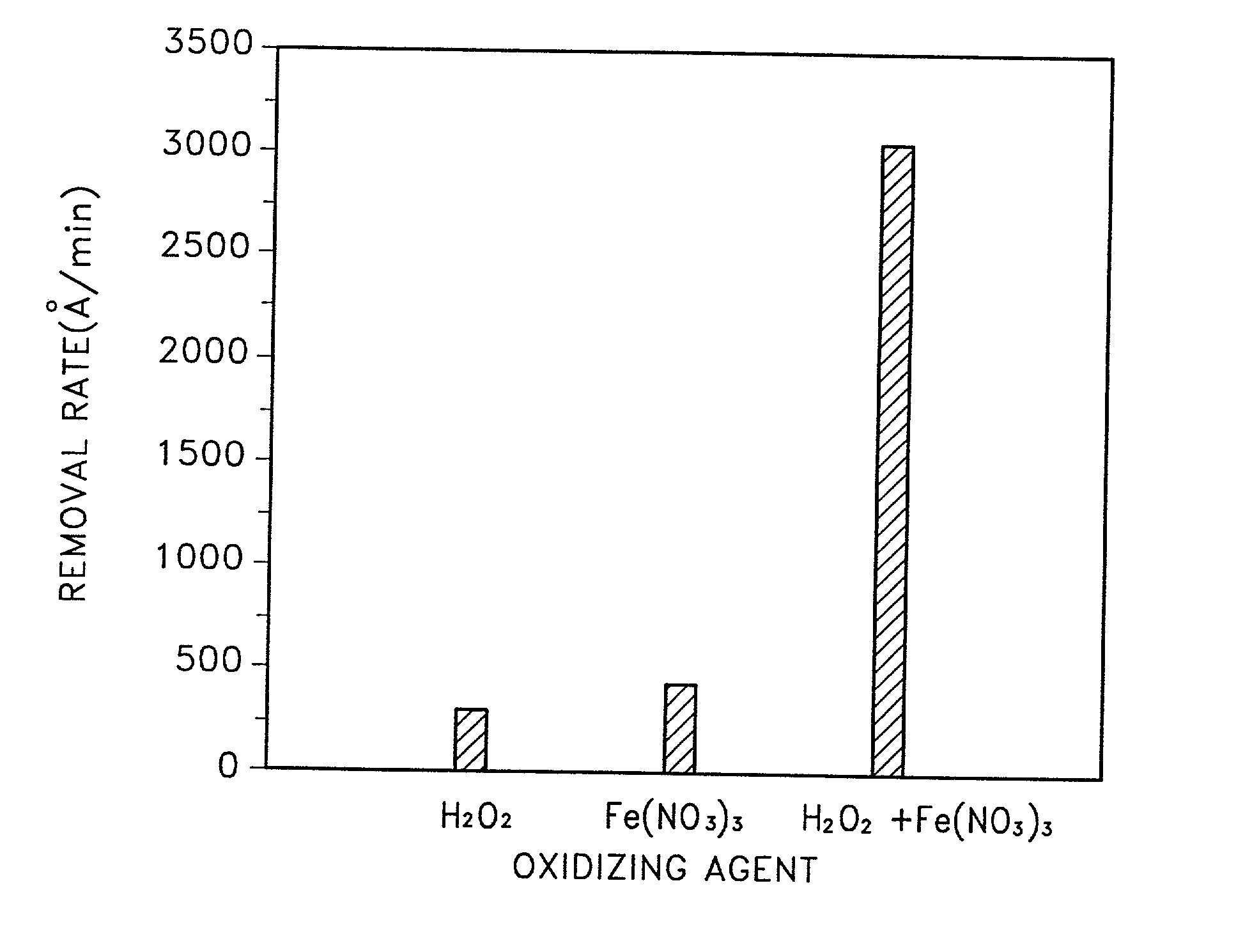
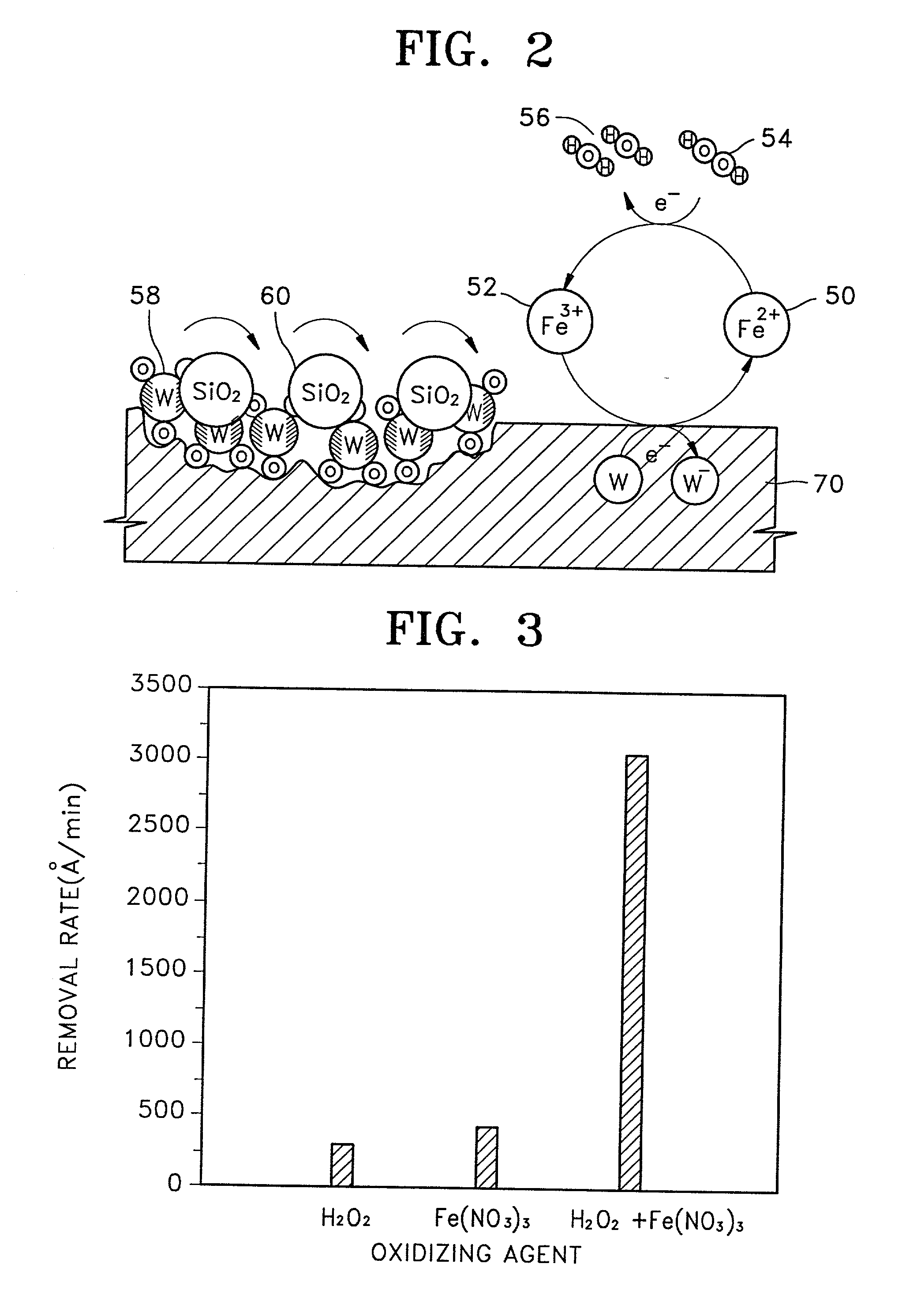
[0076] The removal rates of a tungsten (W) layer and a titanium (Ti) layer with respect to the amounts of the second oxidizing agent in the second solution, and a fluorine compound were evaluated.

[0077] H.sub.2O.sub.2 and Fe(NO.sub.3).sub.3 were used as the first and second oxidizing agents, respectively. While the amount of H.sub.20.sub.2 was fixed at 2% by weight based on the total weight of the slurry, the amount of Fe(NO.sub.3).sub.3 was varied at 0.05, 0.1 and 0.2% by weight. Also, the amount of HF was varied at 0 and 0.01 % by volume based on the total volume of the slurry, thereby resulting in 6 sample slurries.

[0078] To form a W layer to be polished, a high-temperature oxide (HTO) film was deposited over a silicon substrate to a thickness of 1000 .ANG., and a TiN layer and the W layer were deposited in succession to a thickness of 1000 A and 10000 A, respect...


PUM

PropertyMeasurementUnit
pHaaaaaaaaaa
thicknessaaaaaaaaaa
thicknessaaaaaaaaaa

Abstract

A slurry for use in chemical mechanical polishing (CMP) of a metal layer. The CMP slurry includes an abrasive, a plurality of oxidizing agents, a stabilizer including an organic acid having a carboxyl group, a corrosion inhibitor which suppresses corrosion of a metal, a fluorine compound which reduces a difference in removal rates of a metal layer and a barrier layer, and deionized water. The plurality of oxidizing agents include a second oxidizing agent which oxidizes the metal and a first oxidizing agent which restores an oxidizing ability of the second oxidizing agent.

Description

[0001] 1. Field of the Invention[0002] The present invention relates to a chemical mechanical polishing (CMP) slurry for use in the fabrication of semiconductor devices, and more particularly, the present invention relates to a CMP slurry, to a method of preparing the CMP slurry, and to a metallization method using the CMP slurry.[0003] 2. Description of the Related Art[0004] To achieve further miniaturization of semiconductor devices having increased densities and multilevel interconnections, techniques have been utilized which allow for the formation of very fine patterns. The resultant surface structures of such semiconductor devices have become highly complex, and are typically characterized by increased step height differences at interlevel layers formed therein. Generally, such step differences can cause a number of well-known fabrication problems. As such, in an effort to eliminate or minimize step differences within the layers of a semiconductor device as it is manufactured,...

Claims


Application Information

Patent Timeline
Patent Type & Authority Applications(United States)
IPC IPC(8): C09G1/02H01L21/321H01L21/4763
CPCC09G1/02H01L21/3212H01L21/302
Inventor LEE, JONG-WONYOON, BO-UNHAH, SANG-ROK
Owner SAMSUNG ELECTRONICS CO LTD
Why Eureka
Try Eureka