

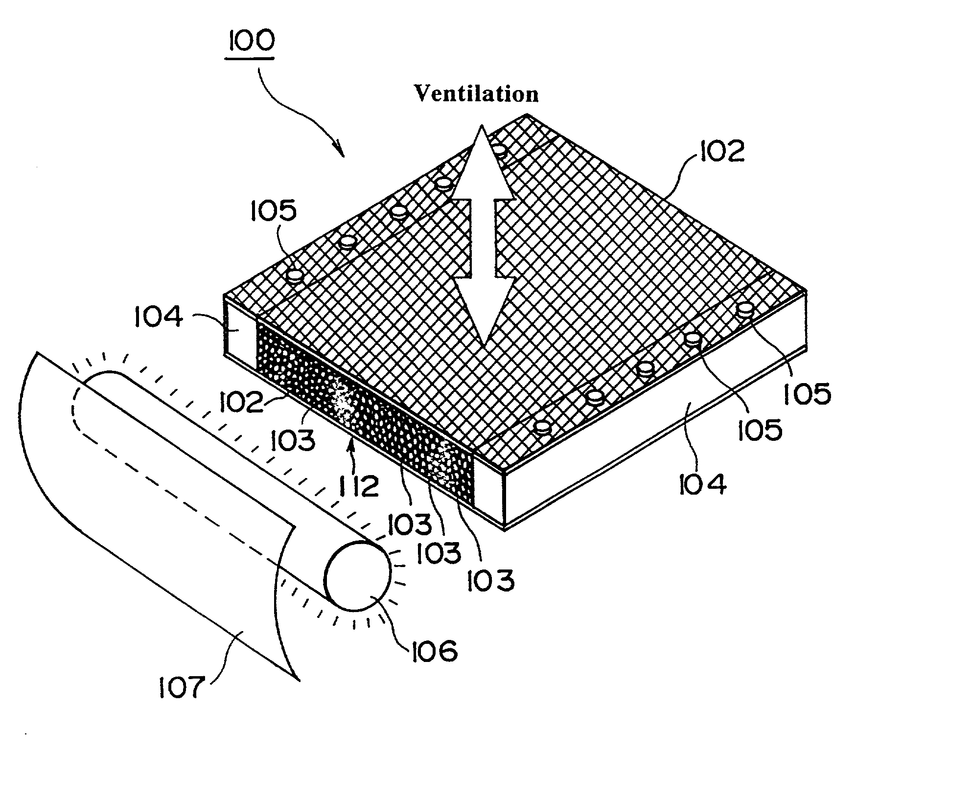
Photocatalytic filter
a filter material and photocatalytic technology, applied in the field of filter materials having photocatalytic activity, can solve the problems of difficult irradiation of the whole surface of a material, low filtering capability, and difficult to achieve effective photocatalytic reaction
- Summary
- Abstract
- Description
- Claims
- Application Information
AI Technical Summary
Benefits of technology
Problems solved by technology
Method used
Image

Examples
example 2 (
first method)
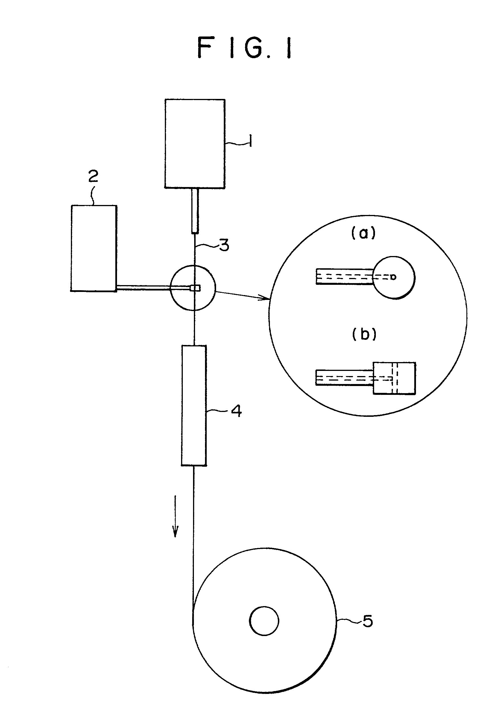
[0115] 1.0 kg of glass beads having the average particle size of 10 .mu.m was suspended into 29.0 kg of a photocatalytic titanium oxide coating liquid (made by Ishihara Techno Co., trade name: ST-KO3, anatase titanium, 5% by weight of particles diffused liquid), thereby preparing a coating liquid.
[0116] The coating liquid was charged into a cylindrical container having the diameter of 100 mm and the length of 700 mm, while applying supersonic waves, and applied to a bundle of glass fibers (about 10,000 glass fibers each having the diameter of 30 .mu.m) by a dip coat method, and heated at 150 degrees, thereby forming the protrusion layer having photocatalysis.
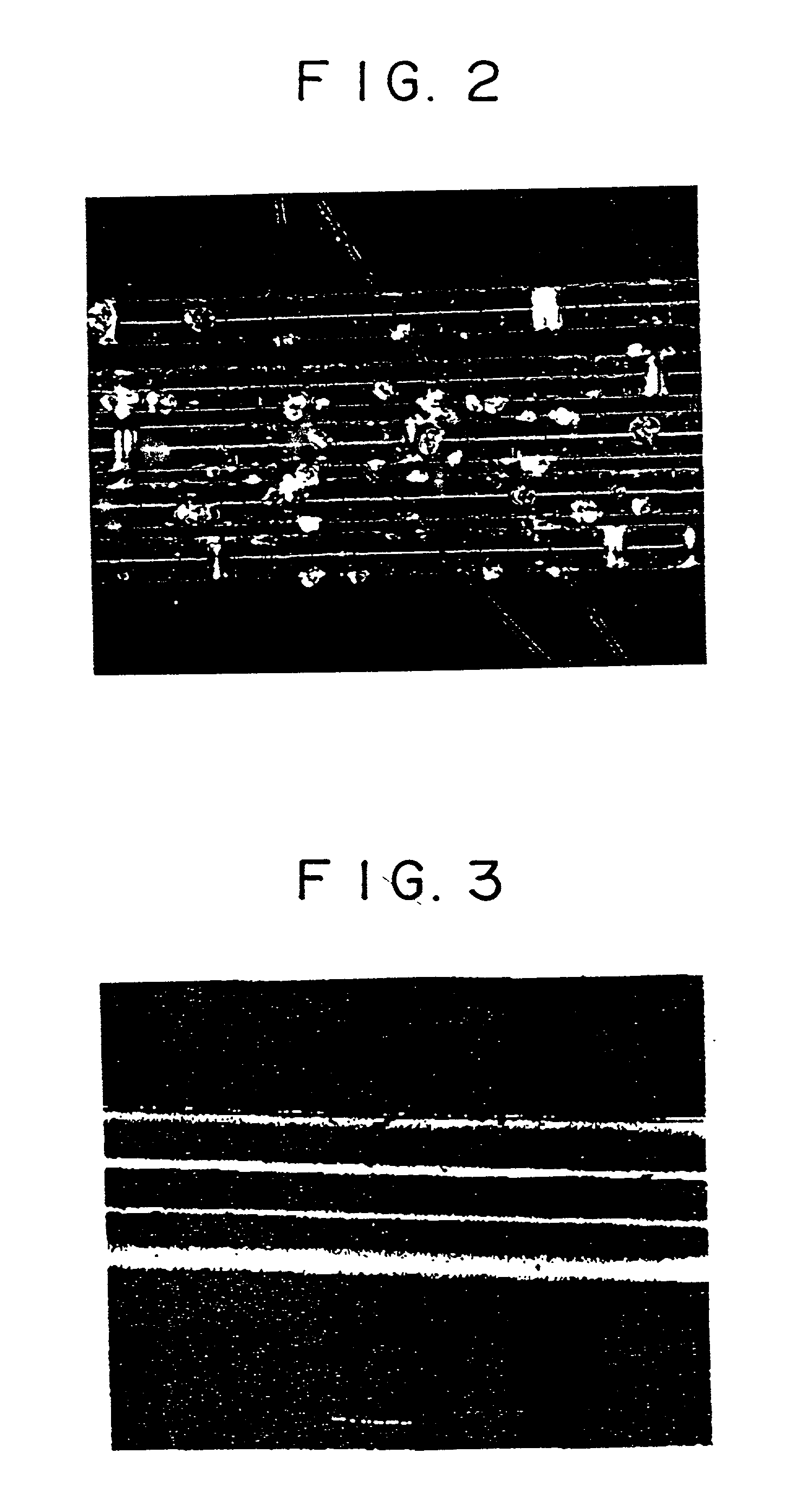
[0117] In the filter material obtained in this manner, the average thickness of the protrusion layer was 11 .mu.m. When the surface was observed by a microscope, it was found that a number of protrusions were formed. Although the filter material was strongly wiped with Kimwipe wet by isopropyl alcohol, the protrusio...
example 3 (
second method)
[0118] While agitating a mixture solution of 3.76 kg of acetylacetone (stabilizer) and 8.84 kg of isopropyl alcohol, 6.39 kg of titanium tetra-n-butoxide was added and the solution was mixed overnight. A mixture solution of 677 g of hydrochloric acid water having the concentration of 0.15 mol / lit. and 8.84 kg of isopropyl alcohol was gradually added to the solution and the resultant solution was agitated for three hours. After that, 1.5 kg of glass beads having the average particle size of 10 .mu.m was suspended, thereby preparing 30 kg of a coating liquid.
[0119] By using the same apparatus (the apparatus shown in FIG. 1) as that of Example 1, the coating liquid was coated on the surface of the glass fiber while pulling the glass fiber in a manner similar to Example 1 and dried at 150 degrees in the heating furnace 4, thereby forming a coating layer made by the glass beads and the precursor of titanium on the surface of the fiber. Heat treatment was performed at 600 de...
example 4 (
second method)
[0122] 1.27 kg of tetraethyl orthosilicate and 3.66 kg of isopropyl alcohol were mixed, 110 g of hydrochloric acid water having the concentration of 0.15 mol / lit. was gradually added, and the resultant solution was agitated for one hour. 4.04 kg of titanium tetra isopropoxide was added to the solution, the resultant solution was further mixed for one hour, 3.70 kg of acetacetateethyl was added, and the resultant solution was agitated overnight. A mixture solution of 731 g of hydrochloric acid water having the concentration of 0.15 mol / lit. and 15.00 kg of isopropyl alcohol was gradually added to the solution and the resultant solution was agitated for three hours. After that, 1.5 kg of glass beads having the average particle size of 5 .mu.m was suspended, thereby preparing 30 kg of a coating liquid.
[0123] By using an apparatus of FIG. 6, as described below, the coating liquid was coated on the surface of the glass fiber, dried, and subjected to heat treatment, thereby ...
PUM
| Property | Measurement | Unit |
|---|---|---|
| Light | aaaaa | aaaaa |
| Refractive index | aaaaa | aaaaa |
Abstract
Description
Claims
Application Information