Iron-based sintered alloy material for valve seat and valve seat made of iron-based sintered alloy

a technology of iron-based sintered alloy and valve seat, which is applied in the direction of engine components, mechanical equipment, machines/engines, etc., can solve the problems of ni and co powder influence on human body remains, high production costs, and high cost of valve seat made of such a sintered alloy, so as to reduce the toughness of the resulting sintered alloy material, the effect of increasing the generation rate of chips and cracks

Inactive Publication Date: 2002-07-04
NIPPON PISTONRING CO LTD
View PDF0 Cites 22 Cited by
  • Summary
  • Abstract
  • Description
  • Claims
  • Application Information

AI Technical Summary

Benefits of technology

[0011] An object of the present invention is to propose an iron-based sintered alloy material for a valve seat, as well as a valve seat made of the iron-based sintered alloy for the use in an internal combustion engine, which solves the aforementioned problems in an advantageous manner, does not contain the alloy elements by large amounts and thus is inexpensive, and exhibits excellent toughness and wear resistance.
[0061] In the iron-base sintered alloy material of the present invention, the solid lubricant particles may optionally be dispersed in the base matrix phase. The solid lubricant particles are preferably at least one type of compound selected from the group consisting of sulfide, fluoride and graphite. Examples of the sulfide include MnS, MoS.sub.2 and W.sub.2S. Examples of the fluoride include CaF.sub.2 and LiF. By dispersing the solid lubricant particles in the base matrix phase, the machinability of the sintered alloy material is facilitated, the wear resistance of the sintered alloy material is enhanced and the aggressieness to mated materials decreases.

Problems solved by technology

As a result, the valve seat made of such a sintered alloy is quite expensive and causes a problem in terms of production cost.
Further, in producing this iron-based sintered alloy, the influence of Ni and Co powder on human body remains as a problem to be solved.
As the iron-based sintered alloy described in JP-A 2000-199040 Laid-Open includes the carbide dispersed phase having relatively high hardness therein by a high proportion the iron-based sintered alloy is quite hard and causes a problem when the sintered alloy is utilized in an application in which excellent toughness is required.

Method used


Image

  • Iron-based sintered alloy material for valve seat and valve seat made of iron-based sintered alloy
  • Iron-based sintered alloy material for valve seat and valve seat made of iron-based sintered alloy
  • Iron-based sintered alloy material for valve seat and valve seat made of iron-based sintered alloy

Examples


Embodiment Construction

[0078] At least one type of powder selected from the group consisting of the iron powder, the alloy iron powder and the alloy elements powder was blended and kneaded with powder of the hard particles (and optionally with the solid lubricant powder) as shown in Table 1, whereby the mixed powder was obtained. The blended amount of each component powder was indicated as wt % with respect to the total amount of the mixed powder.

[0079] The types of the alloy iron powder which was used are: (A) alloy steel powder containing 1.0% of Cr, 0.5% of Mn, 0.3% of Mo and Fe as the remainder; (B) alloy steel powder containing 3.0% of Cr, 0.2% of Mo and Fe as the remainder; (C) alloy steel powder containing 4.0% of Ni, 1.5% of Cu, 0.5% of Mo and Fe as the remainder. Here, "%" represents "wt %".

[0080] The types of the hard particles which were used are: (a) powder of carbide-precipitated particles (the average particle diameter being 80 .mu.m, the average particle diameter of carbide being 3 .mu.m) o...


PUM

PropertyMeasurementUnit
particle diameteraaaaaaaaaa
wt %aaaaaaaaaa

Abstract

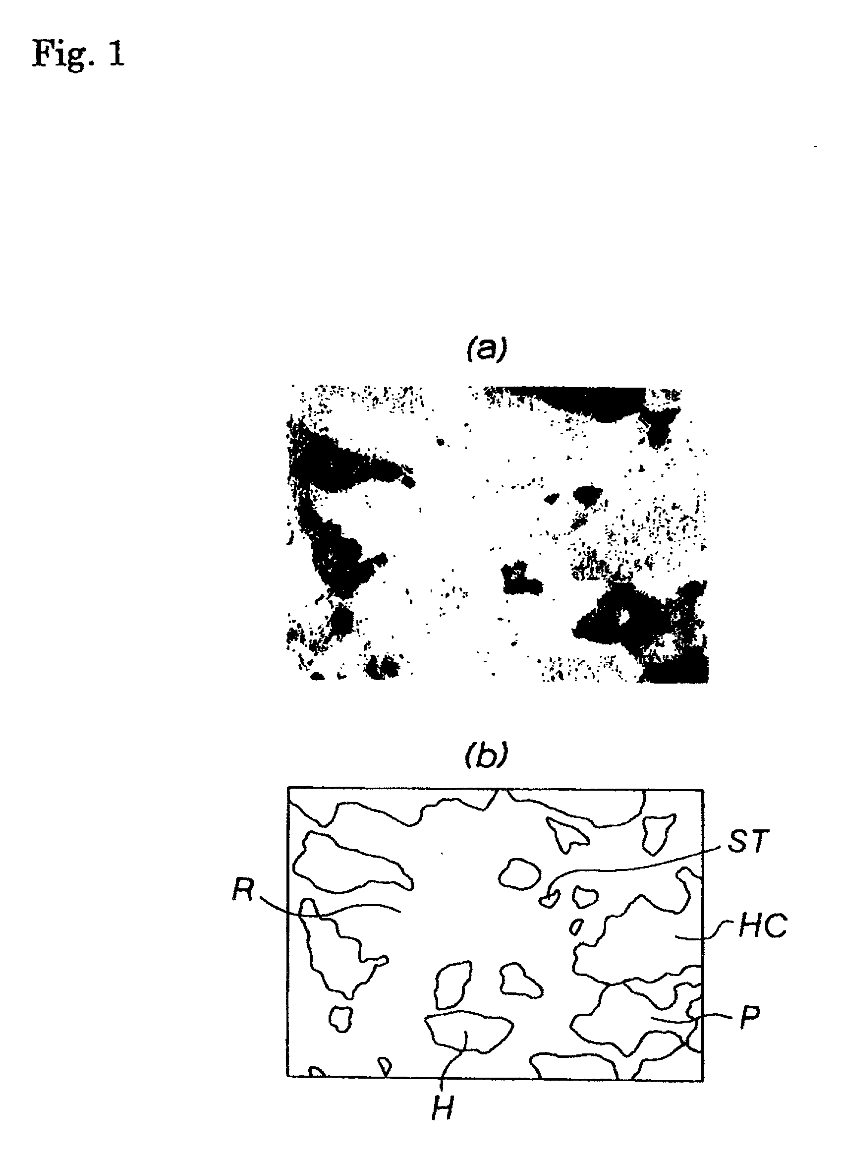
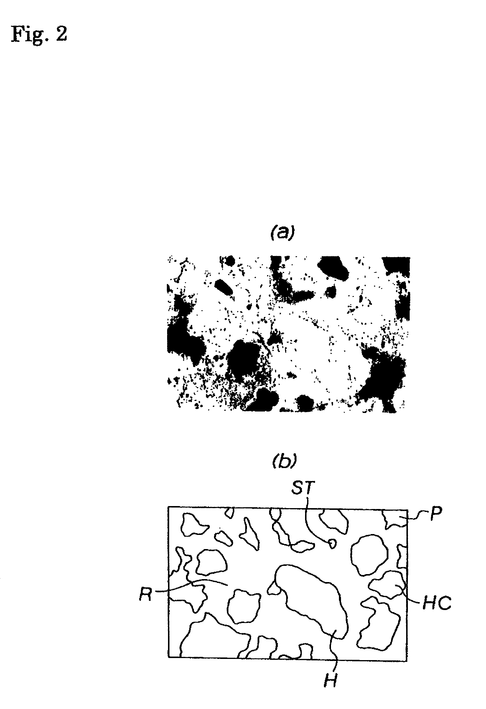
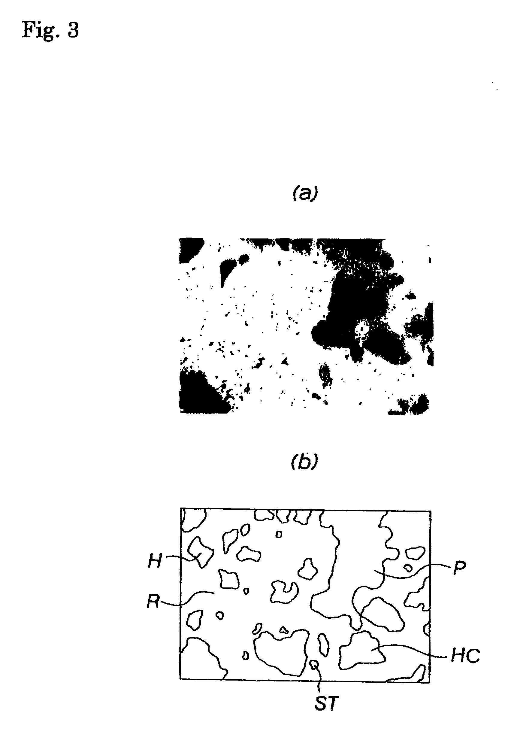
An iron-based sintered alloy material for a valve seat, in which hard particles are dispersed in a base matrix phase, is characterized in that the base matrix phase is comprised of 5 to 40 vol. % of a pearlite phase and 10 to 40 vol. % of a high-alloy diffused phase and particles having hardness of Hv 600 to 1300 and particle diameter of 10 to 150 mum are dispersed as the hard particles, by the amount of 10 to 30 vol. %, in the base matrix phase. The hard particles are preferably at least one type of particles selected from the group consisting of intermetallic compound particles of Mo-Ni-Cr-Si-Co; intermetallic compound particles of Cr-Mo-Co; Fe-Mo alloy particles; and carbide-precipitated particles.

Description

[0001] 1. Field of the Invention[0002] The present invention relates to a sintered alloy material, and specifically to an iron-based sintered alloy material suitable for a valve seat used in an internal combustion engine.[0003] 2. Description of Prior Art[0004] A sintered alloy is produced by a method including the steps of: blending and mixing alloy powder; filling the blended alloy powder in a mold and compression the alloy powder for molding; and sintering the molding in an atmosphere at a predetermined temperature. By this method, according to a sintered alloy, a metal or an alloy which is difficult to obtain by an ordinary melting and casting method can be easily produced In addition, as the various functions can be easily imparted to the product in a combined manner, a member having unique functions can be produced according to this method. Further, a sintered alloy is suitable for producing a porous material, a hard-machining material or a mechanical member having a complicat...

Claims


Application Information

Patent Timeline
Patent Type & Authority Applications(United States)
IPC IPC(8): B22F3/26B22F5/00C22C33/02C22C38/00C22C38/20C22C38/22C22C38/24C22C38/30C22C38/36C22C38/42C22C38/44C22C38/46C22C38/52C22C38/56F01L3/02
CPCB22F2998/00C22C33/0207C22C38/20C22C38/22C22C38/24C22C38/30C22C38/36C22C38/42C22C38/44C22C38/46C22C38/52C22C38/56F01L3/02F01L2101/00F01L2101/02F01L2103/00C22C33/0228C22C33/0242F01L2301/02F01L2301/00F01L2303/00
Inventor TAKAHASHI, TERUOKAKIUCHI, ARATASATO, KENICHI
Owner NIPPON PISTONRING CO LTD
Why Eureka
Try Eureka