Electronic detection of interaction and detection of interaction based on the interruption of flow

a technology of interaction detection and electronic detection, applied in the field of electronic detection of interaction and detection of interaction detection methods based on the interruption of flow, can solve the problems of reducing the effective flow channel diameter of the effective flow channel, inability to achieve the sample preparation process in a chip-scale device, and inapplicability of conventional filters and sample concentrators

Inactive Publication Date: 2002-07-25
MINERVA BIOTECH
View PDF32 Cites 44 Cited by
  • Summary
  • Abstract
  • Description
  • Claims
  • Application Information

AI Technical Summary

Benefits of technology

0030] In some embodiments, chemical, biological, or biochemical agent is allowed to bind at a porous member and thereby collected at the porous member. The agent then is released at a desired point in time and detected downstream. In this manner, the porous member is used to collect, over time, the agent and then to release the agent all at once (or at least in a shorter period of time than the period of time during which it is collected). This can allow very sensitive detection of very low levels of agent by concentrating the agent over time, then releasing the concentrated agent and detecting it.

Problems solved by technology

There is currently no existing technology to accomplish these sample preparation processes in a chip-scale device.
Conventional filters and sample concentrators are impractical because they are constructed of membrane-like materials that require large pressure gradients to force a sample through their small effective diameters open to fluid flow.
Thus, this reduction in effective flow channel diameter can translate into a large pressure drop and resulting upstream pressure requirement that cannot currently be incorporated into a chip-scale device.
Large pressure drops, which are easily generated on bench-top instruments, such a micro centrifuges, cannot be easily generated within micro-devices.
Another impediment to integrating standard sample preparation components into chip-scale sensors is reusability.
Currently available filters are typically single-use, non-reusable components, which, if integrated into chip-scale biosensors, would render these expensive devices single-use and non-reusable.
Additionally, integration of such components would require the use of connectors, which in the micro-scale, have been plagued with leakage and rupture problems.

Method used


Image

  • Electronic detection of interaction and detection of interaction based on the interruption of flow
  • Electronic detection of interaction and detection of interaction based on the interruption of flow
  • Electronic detection of interaction and detection of interaction based on the interruption of flow

Examples


first embodiment

[0104] For example a multiple detection location flow channel system is illustrated in FIG. 8A. As illustrated, a series of probe ligands comprising antibodies, denoted Ab 1-10, can each be immobilized directly to the channel surface or included in a separate nano-net surface immobilized in discrete locations along a single flow path 400. A sensing element, such as a pressure sensor or flow rate detector, etc. 402, is positioned adjacent each discrete region that presents a probe ligand. A sample, suspected of containing a target agent, is mixed with a set of nanoparticles that each present an antibody, denoted Ab A-J. In this system, Ab 1 and Ab A each recognize different epitopes on a first specific target pathogen, as do Ab 2 and Ab B for a second target, Ab3 and Ab C for a third target etc. In this way, the analysis of pressure drop profile through a specific channel 400, at a specified locations, can identify which of a variety of target agents is present in the channel and, th...

example 2

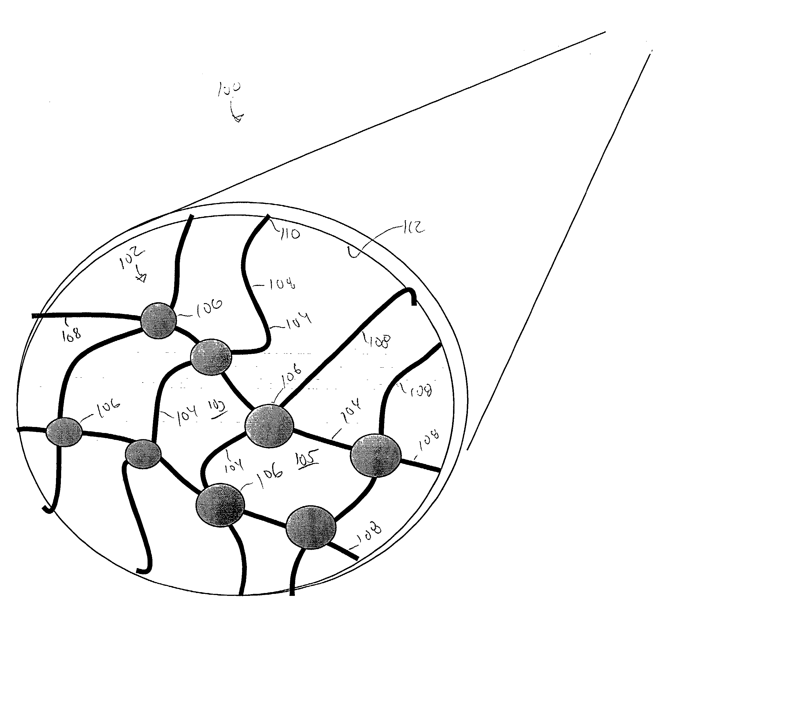
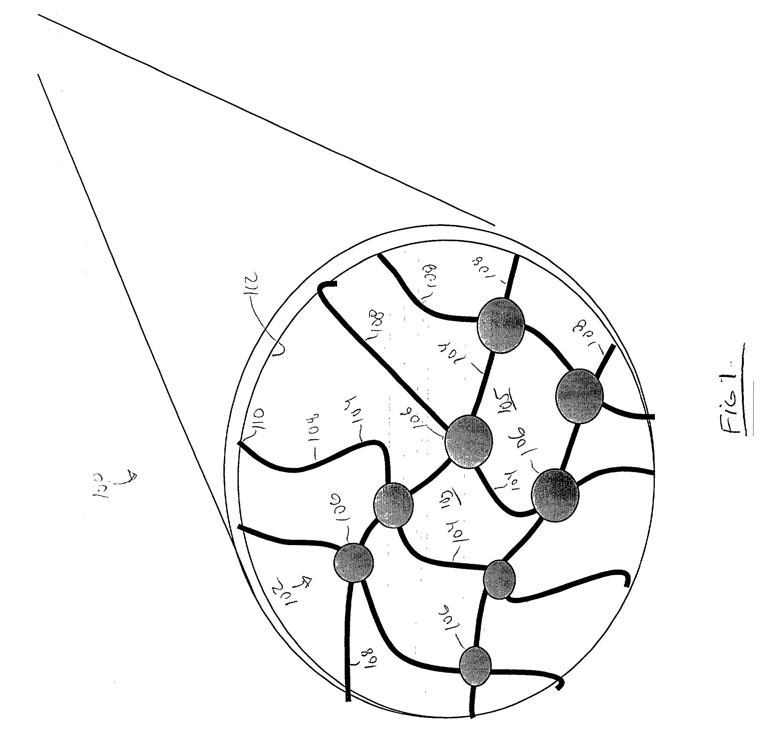
[0109] Forming Nanostructures Comprised of Gold Colloids Linked into a 3-Dimensional Network by Interconnecting DNA.

[0110] FIGS. 5A and 5B are drawings that illustrate the strategy.

[0111] As is familiar to those skilled in the art, double stranded DNA that is modified at each end with a biotin moiety can be generated by performing PCR on a DNA template using biotinylated primers. Both 1 kb and 2 kb DNA fragments were generated to allow formation of nanostructures with different pore size. The PCR products were purified on an agarose gel using standard techniques.

[0112] FIG. 11 is a photocopy of a composite of digital photos and cartoons that illustrate the corresponding experiment. This figure shows that a colloid-DNA nanostructure is formed when biotin-SAM-coated colloids are incubated with streptavidin and biotinylated DNA. The formation of colloid-DNA nanostructures is detected by detecting a color change of the colloid and DNA containing solution. It is an inherent property of g...

example 3

[0114] Reconfigurable Nanostructures.

[0115] Self-assembled 3-dimensional structures that are formed from the interaction of nanoparticles and dsDNA were disassembled and reconfigured in situ. The addition of heated water caused the DNA strands to melt or disassociate. Since each DNA strand was only biotinylated at one end, strand melting caused the nanostructure to disassemble. Experiments pictured in FIG. 12 showed that nanostructures were melted when the solutions were heated. These results indicate that nanoparticle-DNA structures can be configured and reconfigured in situ. The results also argue that what is forming are in fact networks rather than non-specific aggregates, which would not be prone to disassemble. Referring still to FIG. 12, on the left (1) is a photocopy of a photograph of a solution containing biotinylated dsDNA, biotin-SAM-coated gold colloids, and streptavidin; (2) is a photocopy of a photograph of a solution containing biotin-SAM-coated gold colloids, and st...


PUM

PropertyMeasurementUnit
pore sizeaaaaaaaaaa
pore sizeaaaaaaaaaa
pore sizeaaaaaaaaaa

Abstract

Porous members can be positioned so as to partially or fully span channels in microfluidic systems. The porous members can be assembled and/or disassembled in situ. The porous members can be made such that pores are separated by connections including but a single molecule at one location, allowing for a high level of open area in a very small pore size member. The porous member can be made up of colloid particles interconnected with molecular species. These can be used to detect analytes qualitatively and/or quantitatively, or to selectively bind and/or release agents on command for a variety of purposes including first blocking, then opening a channel, concentrating analyte over time followed by release of analyte and detection downstream, etc. Porous members can define valves in multiple-channel systems and, with controlled binding and release of agents at the porous members, these valves can be opened and closed and fluid flow controlled in a multi-channel system. Fluidic systems of the invention can include multiple sensing locations at which different analytes are determined. Systems of the invention provide flexibility for overall microchemical analysis, sequentially, of a variety of agents.

Description

[0001] This non-provisional application claims the benefit under Title 35, U.S.C. .sctn.119(e) of co-pending U.S. provisional application No. 60 / 237,427, filed Oct. 3, 2000 and U.S. provisional application no. 60 / 272,727, filed Mar. 1, 2001, each of which is incorporated by reference herein.FIELD[0002] The present invention relates to novel methods of detection based on the interruption of flow and methods to use this interruption of flow through a channel to redirect flow through a complex circuit of flow channels for detection relating to diagnostics, therapeutics, environmental sampling and food monitoring. The present invention also relates to methods of manipulating and handling samples, suspected of containing a target substance, including biological samples, to detect, separate and / or concentrate target materials such as molecules, biological molecules, cells and spores. The present invention can be utilized for or adapted to multiplexing processes and logical processes inclu...

Claims


Application Information

Patent Timeline
Patent Type & Authority Applications(United States)
IPC IPC(8): B01J20/281B01J20/285C12Q1/00C12Q1/68G01N27/28G01N30/00G01N30/88G01N33/15G01N33/50G01N33/543G01N33/566G01N33/68
CPCB82Y30/00C12Q1/6816G01N33/54326G01N33/54346G01N33/6803G01N2500/00C12Q2565/629C12Q2563/155Y10S436/806Y10T436/143333
Inventor BAMDAD, CYNTHIA C.
Owner MINERVA BIOTECH
Why Eureka
Try Eureka