Crystallizable/non-crystallizable polymer composites

US20020106406A1Inactive Publication Date: 2002-08-08ILLINOIS BOARD OF TRUSTESS OF UNIV OF

Image

  • Crystallizable/non-crystallizable polymer composites
  • Crystallizable/non-crystallizable polymer composites
  • Crystallizable/non-crystallizable polymer composites

Examples


example 1

[0062] A polymer mixture was prepared by mixing PCL with ethyl benzoate in a 10 cm.sup.3 glass vial. In order to effect good solubilization, the mixture was sealed and heated at 50.degree. C. for 24 to 48 hours. The mixture was periodically stirred to disperse lumps and remove trapped air bubbles. Once the polymer was dissolved completely, the solution was cooled to 37.degree. C. and stored. Lysozyme particles were added to the polymer solution at a level of 10% by weight of the total formulation. Composition of the mixture is given in Table 1.

examples 2-4

[0063] Polymer blends were prepared as in Example 1, but using a mixture of PCL and PDLA as the polymeric component. Lysozyme particles were added to the polymer blend solutions. Compositions of the mixtures are given in Table 1.

example 5

[0064] A polymer mixture was prepared as in Example 1, but using PDLA as the polymeric component. Lysozyme particles were added to the polymer solution. Composition of the mixture is given in Table 1.

1 TABLE 1 Composition in weight percent Example PCL PDLA Ethyl benzoate Lysozyme 1 45 0 45 10 2 31.5 13.5 45 10 3 22.5 22.5 45 10 4 13.5 31.5 45 10 5 0 45 45 10

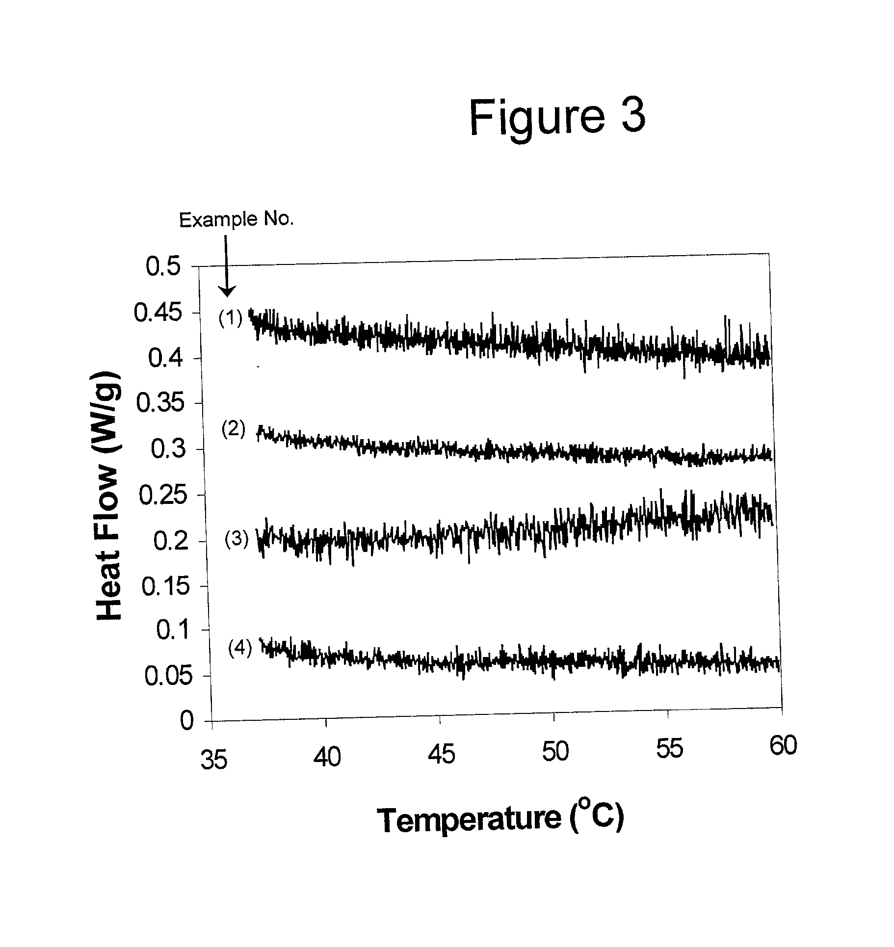
[0065] Crystallization Behavior

[0066] Solutions from Examples 1-4 were analyzed by differential scanning calorimetry (DSC) using a PERKIN ELMER DSC-7 instrument (PERKIN ELMER INSTRUMENTS, Boston, Mass.). The solutions were kept at 37.degree. C. until they were placed in the calorimeter. Data were collected from 37.degree. C. to 60.degree. C. at a heating rate of 1.degree. C. / minute. The scans are shown in FIG. 3. None of the samples gives evidence of a T.sub.m.

[0067] The solutions were separately injected via syringe into an agitated, temperature-controlled PBS bath at 37.degree. C. to form depots. After 4 days, the depots were r...


PUM

PropertyMeasurementUnit
Percent by massaaaaaaaaaa
Compositionaaaaaaaaaa
Miscibilityaaaaaaaaaa

Abstract

A mixture containing a bioactive agent and one or more biodegradable polymers for use as a biodegradable implant is described. Different ratios of semi-crystalline to amorphous polymers in the mixture provide for different release profiles of the bioactive agent from the implant. This system allows tailoring of the release profile by control of the composition of the implant.

Description

[0002] Sustained delivery of bioactive agents, especially peptide- and protein-based drug therapies, have been achieved through the use of biodegradable polymeric implants. Traditionally, this technology has involved surgical implantation of a polymeric monolith containing a suspended bioactive agent. Certain complex shapes of these monoliths have been developed to provide a constant release of the bioactive agent over a period of time. This type of release is described as zero-order as the rate of release is not affected by the concentration of the agent. Zero-order kinetics are desirable for therapies that require the administration of a constant level of a bioactive agent. Polymer microspheres encapsulating a bioactive agent can also be used for controlled release and are generally administered by subcutaneous injection. Although their implantation is easier than that of monoliths, the release mechanism of microspheres is rarely zero-order.[0003] Drug release from polymeric impla...

Claims


Application Information

Patent Timeline
08 Aug 2002
Publication
US20020106406A1
IPC
A61K9/00; A61K9/22; A61K47/34
CPC
A61K9/0024; A61K47/34
Inventors
MCHUGH, ANTHONY J.; DESNOYER, JESSICA R.