Fluorinated solvent compositions containing ozone

a technology of fluorinated solvents and compositions, applied in the field of cleaning compositions, can solve the problems of difficult removal of particles from devices, troublesome stiction, and affecting device performance, and achieve the effect of not being easily recovered

Inactive Publication Date: 2002-08-08
3M INNOVATIVE PROPERTIES CO
View PDF0 Cites 20 Cited by
  • Summary
  • Abstract
  • Description
  • Claims
  • Application Information

AI Technical Summary

Benefits of technology

[0008] In yet another aspect, this invention relates to a cleaning process for substrates comprising contacting a substrate with a liquid cleaning composition comprising a fluorinated solvent and ozone; and then separating the cleaning composition from the processed substrate. The cleaning process makes more efficient use of the available ozone than conventional aqueous processes and achieves an oxidative cleaning rate comparable to that of conventional aqueous oxidative compositions. The present invention also improves safety by avoiding potentially hazardous "RCA" solutions that contain strong acids. The process and composition of this invention may also be used in the cleaning and etching of GaAs devices and substrates.
[0029] Perfluorocarbons, since they lack chlorine atoms, are not ozone-depleting agents, but these compounds may exhibit a global warming potential (GWP) due to their long atmospheric lifetimes. It is preferred that the fluorinated solvent be partially or incompletely fluorinated, i.e. contain at least one aliphatic or aromatic hydrogen atom in the molecule. These compounds generally are very thermally and chemically stable, yet are much more environmentally acceptable in that they degrade in the atmosphere and thus have a low global warming potential, in addition to a zero ozone depletion potential, and better solvency properties.

Problems solved by technology

The etch cleaning and drying of MEMS has similar issues to those for semiconductor chip manufacture.
Particulate contamination on micromachines can hinder movement of the device and ultimately affect device performance or cause failure.
Care is taken to rinse the device with deionized water followed by ethyl alcohol or isopropanol but has similar problems to the IC in that the particles are not easily removed from devices due to the polysilicon surface energy and intricate designs.
The high surface area of these structures along with the tight tolerances between structures makes stiction a very troublesome problem.
The high surface tensions of the aqueous or alcoholic rinses can greatly exacerbate the capillary effects and lead to a higher incidence of microstructure stiction following the release-etch and drying steps.

Method used


Image

  • Fluorinated solvent compositions containing ozone
  • Fluorinated solvent compositions containing ozone
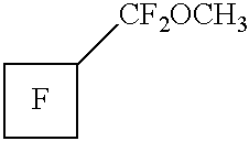
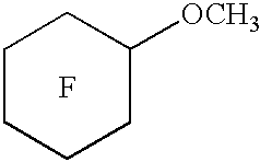
  • Fluorinated solvent compositions containing ozone

Examples


example 1

[0067] A 4 inch (100 mm) diameter silicon wafer, boron doped in the range of 30-60 ohm-cm with (100) orientation, single side polished, with a 200 angstrom layer of thermal silicon dioxide (available from MEMC Electronic Materials, St. Peters, Mo.), was diced into several small pieces, each piece approximately 20 mm.times.20 mm.

[0068] All the silicon wafer pieces were then cleaned using an oxidative cleaning process consisting of simultaneously treatment with ultraviolet light (UV) and ozone using a UV / ozone apparatus consisting of a 500 volt DC power supply and low pressure mercury grid lamp having quartz tubing (available from BHK Inc., Pomona, Calif.). The grid lamp was attached to a 5 in (13 cm).times.5 in (13 cm) piece of polished aluminum that served as the top of the UV / ozone apparatus. Approximately 90% of the lamp intensity was at a wavelength of 254 nm, and approximately 5% was at 185 nm. The wafer pieces were placed on a mobile stage which was raised toward the lamp at th...


PUM

PropertyMeasurementUnit
weight %aaaaaaaaaa
surface tensionaaaaaaaaaa
diameteraaaaaaaaaa

Abstract

A homogeneous non-aqueous composition containing a fluorinated solvent, ozone, and optionally a co-solvent and the use of these compositions for cleaning and oxidizing substrates is described.

Description

[0001] This invention relates to homogeneous non-aqueous compositions containing a fluorinated solvent, ozone, and optionally a co-solvent and the use of these compositions for cleaning and processing semiconductors and integrated circuits including silicon and Ga / As substrates.[0002] The use of microelectronic devices, such as integrated circuits, flat panel displays and micro electromechanical systems, has burgeoned in new business and consumer electronic equipment, such as personal computers, cellular phones, and electronic calendars. Such devices have also become an integral part of more established consumer products such as televisions, stereo components and automobiles.[0003] These devices in turn contain one or more very high quality semiconductor chips made from silicon wafers containing many layers of circuit patterns. Typically nearly 350 processing steps are required to convert a bare silicon wafer surface to a semiconductor chip of sufficient complexity and quality to be...

Claims


Application Information

Patent Timeline
Patent Type & Authority Applications(United States)
IPC IPC(8): C11D7/02C11D7/26C11D7/32C11D7/50C11D11/00H01L21/304H01L21/306
CPCC11D3/3947C11D7/263C11D7/264C11D7/265C11D7/266C11D7/32C11D7/3263C11D7/3281C11D7/5018C11D11/0047H01L21/02052Y10S134/902C11D7/02H01L21/02082
Inventor ZAZZERA, LAWRENCE A.BEHR, FREDERICK E.PARENT, MICHAEL J.RAJTAR, PAUL E.
Owner 3M INNOVATIVE PROPERTIES CO
Why Eureka
Try Eureka