Method for manufacturing a single high-temperature fuel cell and its components

a high-temperature fuel cell and manufacturing method technology, applied in the direction of fuel cells, electrochemical generators, electrical equipment, etc., can solve the problems of increasing and complicated specific demands on htfc construction, limiting the application of known ceramic technologies and materials in forming htfc components, and inability to divide and independent cell manufacturing conditions

Inactive Publication Date: 2002-09-05
GORINA LILIYA FEDOROVNA +7
View PDF0 Cites 37 Cited by
  • Summary
  • Abstract
  • Description
  • Claims
  • Application Information

AI Technical Summary

Problems solved by technology

Moreover, since all components of the HTFCs are in a solid state, the ceramic fuel cells, for example, can be formed into ultra-thin layers, and the cell's elements can be shaped into unique forms unachievable in liquid electrolyte fuel cell systems.
Moreover, methods for manufacturing the components of ceramic fuel cells must be compatible, because cell manufacturing conditions cannot be divided and independent for each component.
However, increasing and complicated specific demands made on HTFC construction, such as:
substantially limit the application of known ceramic technologies and materials when forming HTFC components such as the electrodes, the electrolytes, and the current passages.
One of the limitations is conditioned by great differences in caking temperatures of the materials, at which the HTFC components being mated are manufactured.
Therefore, special methods for forming the solid oxide electrolytes and the electrodes developed recently appear to be inefficient.
This change may be accompanied by irregular shrinkages of various HTFC components, and increased mutual diffusion between components, which may lead to component failure or to unacceptable decreases in desired article features.
The manufacture of the individual components of an HTFC is performed by various technologies, which finally complicates the process of manufacturing the HTFC as a whole and particularly complicates its hardware realization.
After performing this analysis, a tendency develops to use different classes of organic substances, which ultimately leads to inevitable widening in the range of substances and materials used, and subsequently a rise in the cost of manufacturing the HTFC as a whole.
The first two requirements appear to contradict each other, therefore the problem of finding a compromise always exists in practice.
However, due to their high cost, the noble metals such as platinum, palladium, and silver are practically used in SOFCs for research purposes only.
This, in its turn, does not allow the diffusion and strength characteristics of the porous carrier cathode to vary.
Moreover, caking at high temperatures assumes higher power expenses for manufacturing the fuel cells.
Besides limitations inherent to known similar designs, the solid-phase synthesis used in the technology protected by this patent does not provide the homogenous characteristics of the powder.
The caking process is performed at high temperatures with significant shrinkages, thereby requiring additional techniques to obtain articles of a required size, i.e. the technology is sufficiently labor-consuming and power intensive.
The most labor intensive problem is to create a technology of applying gas-dense layers (.sigma. is equal of 1 to 40 .mu.m) of electrolytes on the carrier (both gas-dense and porous).
The thin-film, design has a particular significance for the construction of the proton electrolytes, because in this case the main disadvantages come from resistive loss, and the substantially lower mechanical strength of the BaCeO.sub.3 ceramic electrolyte, as compared to that of ZrO.sub.2.
Therefore this material cannot simultaneously perform the two functions of the carrier element construction material and the electrolyte.
The technical problems of manufacturing a thin-film electrolyte are complemented by the high cost of the manufacturing technology.
Thus, even if all technical problems were solved, the technology would contemplate the maintenance of parameters in order to obtain reproducible characteristics, for example, to control the temperature to within an accuracy of 2 degrees, would require an unacceptably expensive and possibly unreliable technology.
Currently known methods for two-stage high-temp

Method used


Image

  • Method for manufacturing a single high-temperature fuel cell and its components
  • Method for manufacturing a single high-temperature fuel cell and its components
  • Method for manufacturing a single high-temperature fuel cell and its components

Examples


example 2

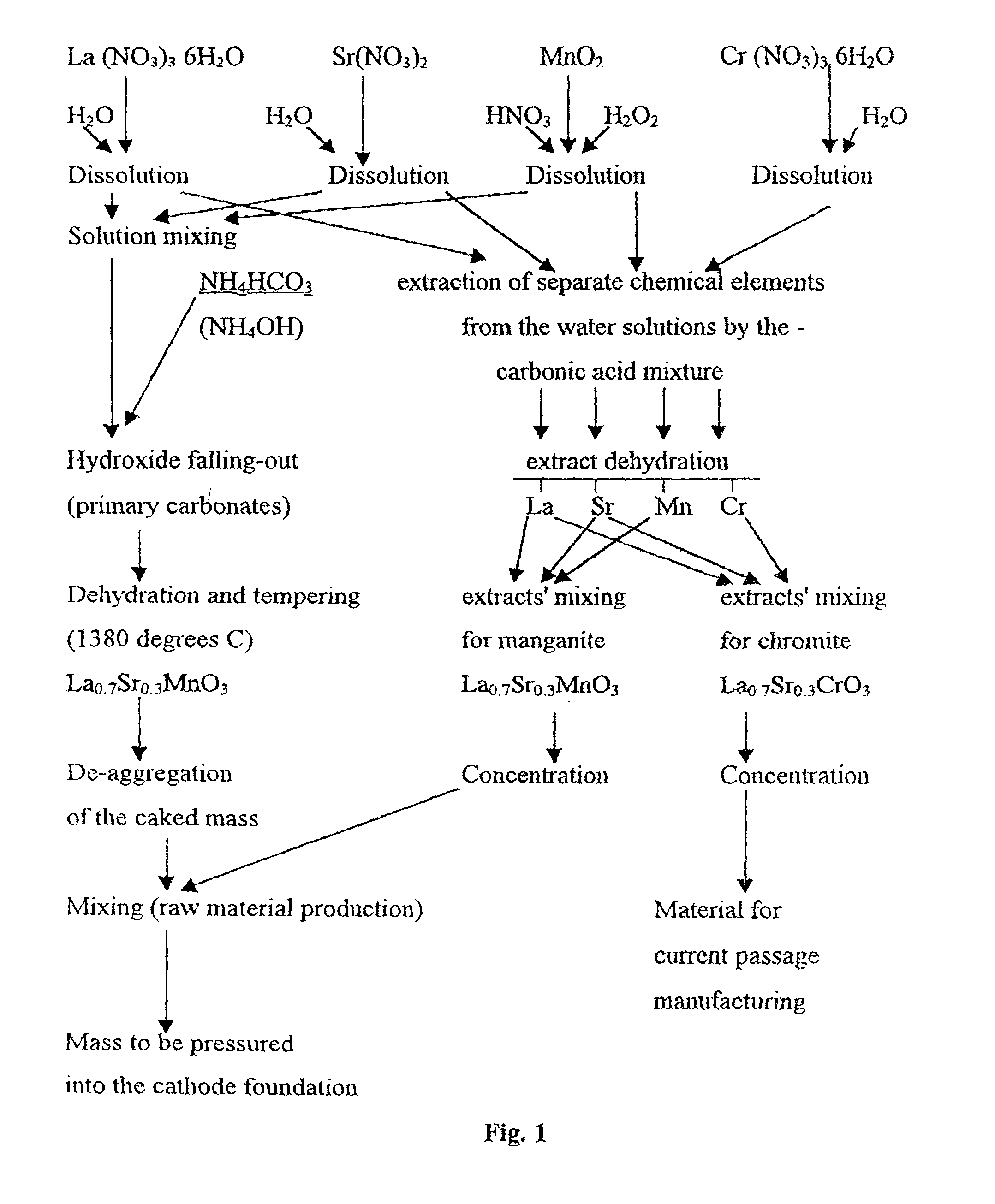
[0237] A mixture of La.sub.0.7Sr.sub.0.3MnO.sub.3 powder and the solution of La, Sr, Mn carboxylates were prepared as described in the Example 1. The obtained mixture was heated, in air. to a temperature of 650.degree. C. for 45 minutes. The obtained powder was deaggregated, in order to destroy any unstable aggregates formed after thermal treatment. Further steps of manufacturing the tubular cathodes are similar to those indicated in the Example 1. The tube caking temperature was 1380.degree. C. The results of changing the strength of the articles are presented in Table 3.

5TABLE 3 N.sup.o of preliminary Porosity, Bending strength treatment cycles % kg per sq. cm 1 29.0 72.0 2 28.6 75.8 3 27.9 76.4 4 27.3 77.0 5 27.1 77.0

example 3

[0238] The powder of the La.sub.0.7Sr.sub.0.3MnO.sub.3 composition used in examples 1 and 2 was mixed with a mixture of carboxylates containing Co, La, and Sr in proportions corresponding to the La.sub.0.6Sr.sub.0.4CoO.su-b.3 composition. The indicated carboxylates were obtained by extracting the corresponding metals. The total concentration of metals was 291 g per kg. The tube manufacture was performed as indicated in example 1. The results of caking the tubes at various temperatures are presented in Table 4.

6TABLE 4 Bending N.sup.o of Caking Parameters strength, kg sample T, .degree. C. Time, Hour Porosity % per sq. cm 1 1200 1 39.0 55.0 2 1250 1 37.5 57.0 3 1300 1 32.2 70.0 4 1350 1 30.0 74.0

Preferred Embodiment of the Invention for Manufacturing the Interface Layer

example 4

[0239] In order to manufacture the interface layer, a CLS film of 0.3 to 0.6 .mu.m in thickness is applied onto the carrier porous cathode from the MLS manufactured as described in the example 1. The step of applying is performed by painting the cathode surface, heated up to 530.degree. C, with the mixture of Cr, La, Sr carboxylates in the air atmosphere. The total concentration of Cr, La, Sr in the mixture of the carboxylates (converting to oxides) was 30 g per kg. The organic component of the carboxylates is represented by the mixture of the following composition:

7 Dimethyl-propyl-acetic acid C.sub.7H.sub.14O.sub.2 36% by weight, Dimethyl-butyl-acetic acid C.sub.8H.sub.16O.sub.2 31% by weight, Dimethyl-amyl-acetic acid C.sub.9H.sub.18O.sub.2 15% by weight, Dimethyl-hexyl-acetic acid C.sub.10H.sub.20O.sub.2 7% by weight, Dimethyl-lauryl-acetic acid C.sub.12H.sub.24O.sub.2 2% by weight.

[0240] The proportion of Cr, La, and Sr oxides after decomposing the mixture of carboxylates on th...


PUM

PropertyMeasurementUnit
Fractionaaaaaaaaaa
Fractionaaaaaaaaaa
Fractionaaaaaaaaaa

Abstract

This invention relates to prospective electric energy sources to be employed in both mobile and stationery high-power electric stations. A method is disclosed for manufacturing a High Temperature Fuel Cell (HTFC), and the associated components, having a solid oxide electrolyte, and designed to transform chemical energy directly into electrical power. The disclosed method for manufacturing an HTFC and its components employs a narrow class of organic reagents which are well known, and widely used in the art. The manufacturing and assembly is performed within the framework of a single physical/chemical process and uniform technological equipment.

Description

[0001] This application is a continuation application of U.S. patent application Ser. No. 09 / 308,013, filed May 11, 1999 which is a U.S. national phase under 35 U.S.C. .sctn.371 of International Application No. PCT / RU97 / 00159, filed May 23, 1997, which claims priority to Russian application RU 96 / 00319, filed Nov. 11, 1996.[0002] This invention relates generally to the field of direct conversion of chemical energy into electrical power, and more particularly, to high-temperature electrochemical devices (HTECD) with solid oxide electrolytes (SOE) which may be used for manufacturing high-temperature fuel cells (HTFC) components thereof.[0003] High-temperature fuel cells are currently among the most promising sources of electrical power both in mobile systems and stationary high-power electric stations. Additionally, HTFCs are being considered as an alternative to nuclear power.[0004] One important feature of HTFCs is the ability for the direct conversion of the chemical energy stored ...

Claims


Application Information

Patent Timeline
IPC IPC(8): H01M4/86H01M4/90H01M6/00H01M8/10H01M8/12
CPCH01M4/9033H01M4/9066H01M8/1206H01M8/1253Y02E60/521Y02E60/525Y10T29/49115H01M8/1231Y02E60/50Y02P70/50
Inventor GORINA, LILIYA FEDOROVNASEVASTYANOV, VLADIMIR VLADIMIROVICHMOROZOV, VLADIMIR VITALIEVICHNIKITIN, SERGEI VASILIEVICHLIPILIN, ALEXANDER SERGEEVICHRODIONOV, IGOR VLADIMIROVICHSEVASTYANOV, ALEXANDER VLADIMIROVICHYATLUK, JURY GRIGORIEVICH
Owner GORINA LILIYA FEDOROVNA
Why Eureka
Try Eureka