Optical converter flex assemblies

a technology of optical converters and assemblies, applied in the direction of optical elements, instruments, high frequency circuit adaptations, etc., can solve the problems of more sensitive to optical misalignment, and achieve the effects of less rigidity, minimal loss, and increased flexibility

Inactive Publication Date: 2002-09-12
BLAZE NETWORK PRODS
View PDF0 Cites 39 Cited by
  • Summary
  • Abstract
  • Description
  • Claims
  • Application Information

AI Technical Summary

Benefits of technology

0020] A unique feature of the present design of the flexible circuit board is the cross hatch of the ground layer below the signal trace. Typically, a microstrip transmission line uses a solid ground plane. The cross-hatched design relieves portions of the metallization below the signal layer and yet is able to maintain the desired transmission line properties. Still another feature of the design of the flexible circuit board is the use of a liquid photo imageable (LPI) solder mask, which provides additional flexibility because it is less rigid than polyimide material and is not as thick.
0021] The present invention provides Electrical to Optical (E to O) conversion circuits where the transmission of the electrical signals to the converter circuits is accomplishe...

Problems solved by technology

Due to its added complexity, such a design...

Method used


Image

  • Optical converter flex assemblies
  • Optical converter flex assemblies
  • Optical converter flex assemblies

Examples


Embodiment Construction

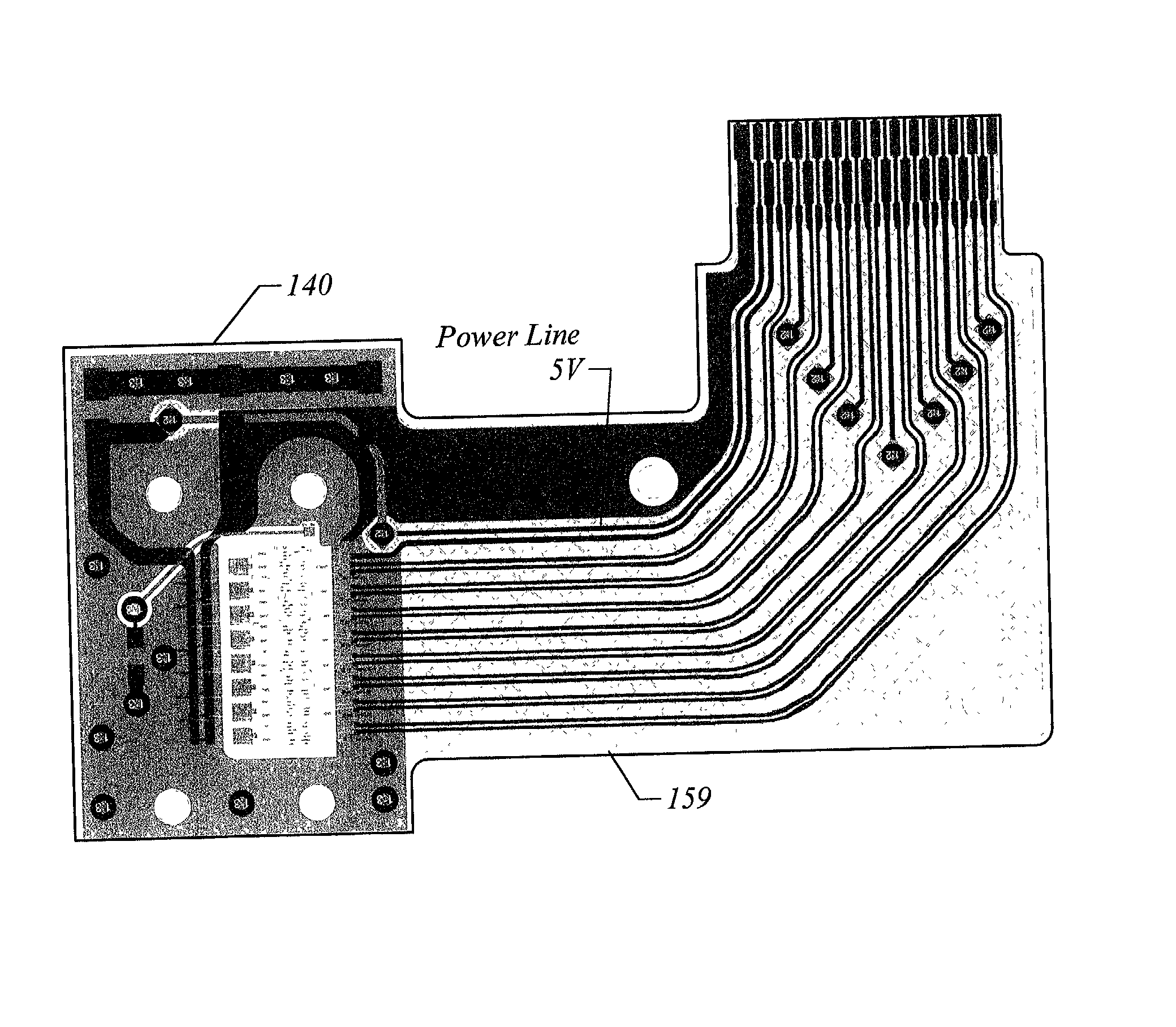
[0048] An aspect of the present invention achieves good long-term optical alignment by providing mechanical isolation of a ceramic substrate relative to the optical components such as lenses. This is accomplished by rigidly attaching the plastic optical portion of the conversion assemblies directly to a housing. Examples of wavelength division multiplexers and / or demultiplexers that may be housed in the plastic optical portion are described in the parent application and in commonly owned U.S. Pat. No. 6,201,908, titled "Optical Wavelength Division Multiplexer / Demultiplexer Having Preformed Passively Aligned Optics," incorporated herein by reference. The ceramic with its associated circuitry is also rigidly attached to the plastic optic. Electrical transmission line connections to and from the optical conversion circuits on the ceramic substrates are made via flexible circuit board designs. This flexible transmission line connection prevents any forces from acting on the ceramic and ...


PUM


Abstract

Optical to electrical and electrical to optical conversion assemblies provide precise and stable alignment, low loss, unperturbed electrical transmission and high thermal conductivity. Mechanically isolating the ceramic substrate of the conversion assembly relative to the surrounding structures enables good long-term optical alignment. Electrical transmission line connections to and from the optical conversion circuits on the ceramic substrates are made via flexible circuit board designs. The alignment of the components on the substrate relative to the plastic optics is thus preserved. The flexible circuit board includes a cross hatched ground layer, which relieves portions of the metallization below the signal layer and yet is able to maintain the desired transmission line properties. Electrical to optical conversion circuits are provided where the transmission of the electrical signals to the converter circuits is accomplished with minimal loss and with good signal integrity.

Description

CROSS-REFERENCE TO RELATED APPLICATION[0001] This application is a continuation-in-part of U.S. patent application Ser. No. ______, titled "Optical Wavelength Division Multiplexer and / or Demultiplexer Mounted in a Pluggable Module," filed on Mar. 12, 2001, and incorporated herein by reference.BACKGROUND OF THE INVENTION[0002] 1. Field of the Invention[0003] The present invention relates to optical to electrical and electrical to optical conversion assemblies used in fiber optic communication, and more specifically, it relates to designs for isolating the conversion assemblies from forces that could cause misalignment of the optical and electrical components and for improving the performance of the conversion assemblies.DESCRIPTION OF RELATED ART[0004] Optical to Electrical (O to E) and Electrical to Optical (E to O) conversion assemblies often require precise and stable alignment, low loss, unperturbed electrical transmission and high thermal conductivity. A variety of methodologies...

Claims


Application Information

Patent Timeline
IPC IPC(8): G02B6/42H05K1/02H05K1/03H05K1/14H05K3/36
CPCG02B6/4292H05K1/0237H05K1/0253H05K1/0306H05K1/147H05K3/361H05K2201/0715H05K2201/09681G02B6/4283G02B6/4261G02B6/4274G02B6/4281
Inventor SUTHERLAND, ROBERT A.SACKS, JAMES S.GRANN, ERIC B.HERRITY, KENNETH R.GRIFFIS, JEFFREY A.JACOBSON, FRANK W. JR.
Owner BLAZE NETWORK PRODS
Why Eureka
Try Eureka