
Anastomosis system and related Methods

a technology of anastomosis and fusion, applied in the field of vascular anastomosis, can solve the problems of insufficient blood flow, depriving the heart muscle of oxygen and nutrients, and even death, and achieve the effect of effectively fuses the graft condui

Inactive Publication Date: 2002-09-12
MAQUET CARDIOVASCULAR LLC
View PDF0 Cites 48 Cited by
  • Summary
  • Abstract
  • Description
  • Claims
  • Application Information

AI Technical Summary

Benefits of technology

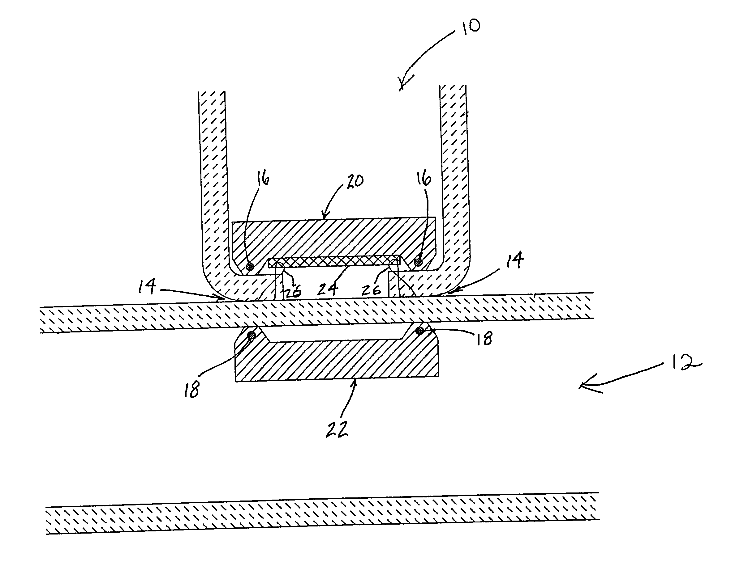
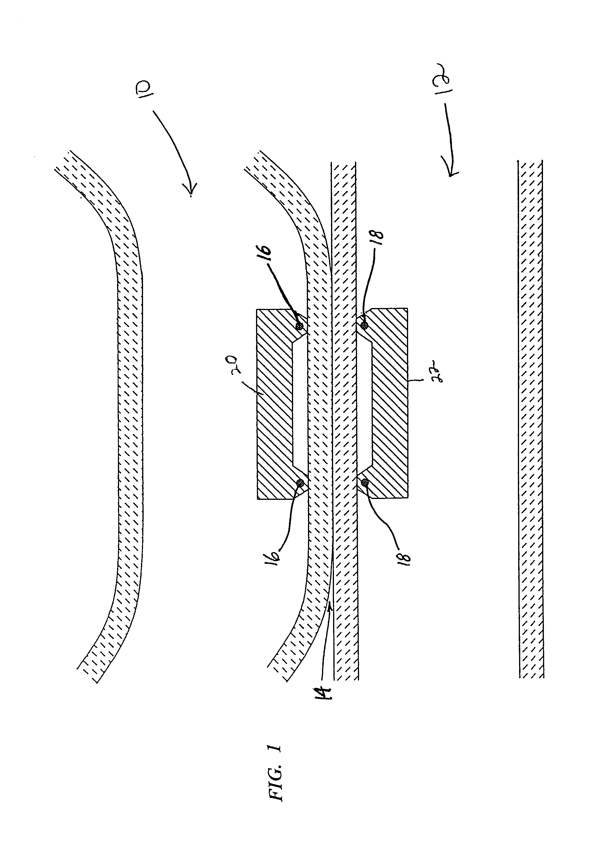
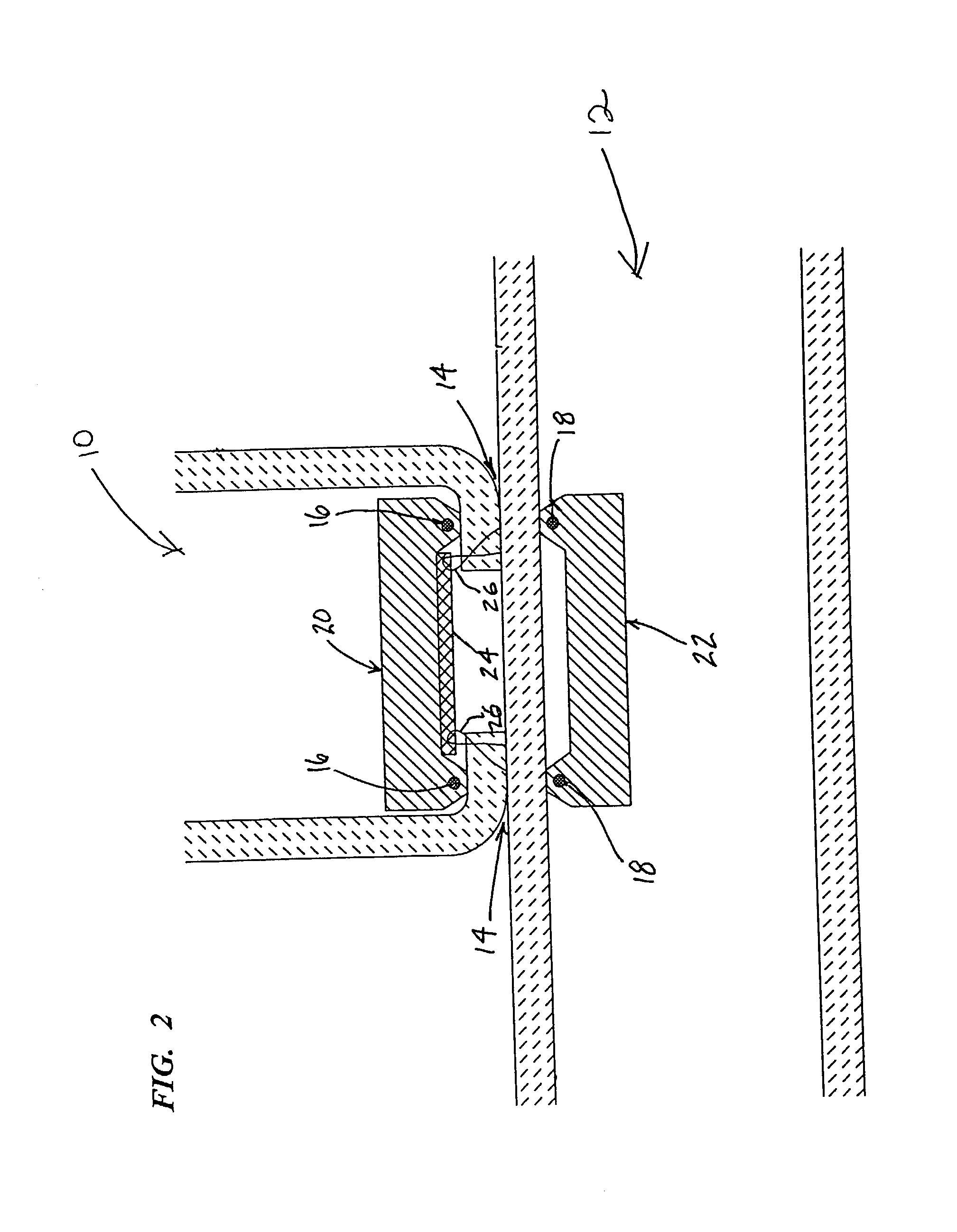
[0015] The present invention involves an anastomosis system and method suitable, by way of example, for use in establishing fluid communication between a graft conduit and a blood vessel in coronary artery bypass graft (CABG) surgery. The anastomosis system of the present invention establishes such fluid communication by employing tissue fusion technology to effectively fuses the graft conduit to the blood vessel, thereby eliminating the need for connectors or similar prior art devices that remain implanted following the anastomosis procedure. The system may be used to create side-to-side and / or end-to-side anastomosis connections. It may also be employed in either open-chest or closed chest procedures.

Problems solved by technology

This results in insufficient blood flow and deprives the heart muscle of oxygen and nutrients, leading to ischemia, possible myocardial infarction, and even death.
For example, it is difficult to perform and requires great skill and experience on the part of the surgeon due in large part to the extremely small scale of the vessels.
In closed-chest or port access procedures, the task of suturing is even more challenging due to the use of elongated instruments positioned through the access ports for approximating the tissues and for holding and manipulating the needles and sutures used to make the anastomoses.
Other drawbacks of connection with stitches are the long duration of the operation, during which period in conventional open-heart CABG surgery the heart is arrested and the patient is maintained under cardioplegic arrest and cardiopulmonary bypass.
Cardiopulmonary bypass has been shown to be the cause of many of the complications that have been reported in conventional CABG, such as stroke.
At present, however, safe, reproducible, and precise anastomosis between a stenotic coronary artery and a bypass graft vessel presents numerous obstacles including continuous cardiac translational motion which makes meticulous microsurgical placement of graft sutures extremely difficult.
The constant translational motion of the heart and bleeding from the opening in the coronary artery hinder precise suture placement in the often tiny coronary vessel.
However, no permanently satisfactory results have been reported with the use of rigid rings.
A rigid ring presents a foreign body of relatively heavy weight which does not heal well and produces pressure necrosis.
Moreover, the use of rigid rings that completely encircle the graft vessel and the arteriotomy creates a severe "compliance mismatch" relative to both the coronary artery and the graft vessel and the anastomosis site which could lead to thrombosis.
However, this device can only perform end-to-end anastomoses such that the coronary artery must first be severed and dissected from the surrounding myocardium and the exposed end everted for attachment.
This technique is limited to cases where the coronary artery is totally occluded and there is no loss of blood flow by completely severing the coronary artery downstream of the blockage to make the anastomosis.
Consequently, this device is not applicable where the coronary artery is only partially occluded and is not at all applicable to making the proximal side-to-end anastomosis between a bypass graft and the aorta.
However, this device does not provide a complete system for quickly and automatically performing an anastomosis.
One of the more difficult maneuvers in applying the staple involves carefully everting the graft vessel over the sharpened ends of the staple legs, then piercing the everted edge of the vessel with the staple legs.
Experimental attempts to apply this technique have proven to be very problematic because of difficulty in manipulating the graft vessel and the potential for damage to the graft vessel wall.
Once the distal lines of the staple have been deformed, it may be difficult to insert the staple through the aortotomy opening.
Another disadvantage of the device of the '447 patent is that the distal lines of the staple pierce the wall of the graft vessel at the point where it is everted over the staples.
Piercing the wall of the graft vessel potentially invites leaking of the anastomosis and may compromise the structural integrity of the graft vessel wall, serving as a locus for a dissection or even a tear which could lead to catastrophic failure.
Because the staple legs only apply pressure to the anastomosis at selected points, there is a potential for thrombosis.
There is also the potential that exposure of the medial layers of the graft vessel where the staple pierces the wall could be a site for the onset of intimal hyperplasia, which would compromise the long-term patency of the graft.
Firstly, the anastomotic fittings described expose the foreign material of the anastomotic device to the blood flow path within the arteries.
This is undesirable because foreign materials within the blood flow path can have a tendency to cause hemolysis, platelet deposition and thrombosis.
The anastomotic fitting of the '819 patent also has the potential drawback that the spikes that hold the graft vessel onto the anastomotic fitting are very close to the blood flow path, potentially causing trauma to the blood vessel that could lead to leaks in the anastomosis or compromise of the mechanical integrity of the vessels.
However, this device is awkward for use in end-to-side anastomosis and tends to deform the target vessel; therefore it is not currently used in CABG surgery.
Due to the delicate process needed to insert the vessels into the device, it would also be unsuitable for port-access surgery.

Method used


Image

  • Anastomosis system and related Methods
  • Anastomosis system and related Methods
  • Anastomosis system and related Methods

Examples


Embodiment Construction

[0035] Illustrative embodiments of the invention are described below. In the interest of clarity, not all features of an actual implementation are described in this specification. It will of course be appreciated that in the development of any such actual embodiment, numerous implementation-specific decisions must be made to achieve the developers' specific goals, such as compliance with system-related and business-related constraints, which will vary from one implementation to another. Moreover, it will be appreciated that such a development effort might be complex and time-consuming, but would nevertheless be routine undertaking for those of ordinary skill in the art having the benefit of this disclosure. It is furthermore to be readily understood that, although discussed below primarily within the context of coronary artery bypass graft surgery (CABG), the anastomosis system of the present invention may be employed in any number of applications and / or procedures wherein it is des...


PUM


Abstract

Devices and methods for sealingly joining a graft vessel, such as a coronary bypass graft, to the side wall of a target vessel, such as the aorta or a coronary artery, in an anastomosis.

Description

RELATED APPLICATION[0001] This application claims the benefit of U.S. Provisional Application Serial No. 60 / 266,694 filed Feb. 5, 2001.FIELD OF THE INVENTION[0002] The present invention relates generally to medical devices and methods for welding biological tissue. In particular, the invention relates to performing a vascular anastomosis and, more particularly, to preferred devices and methods for sealingly joining a graft vessel, such as a coronary bypass graft, to the side wall of a target vessel, such as the aorta or a coronary artery, in an anastomosis.BACKGROUND OF THE INVENTION[0003] A wide variety of medical procedures involve creating an anastomosis to establish fluid communication between two tubular conduits or organs in a patient. Coronary artery bypass graft (CABG) surgery, for example, often involves creating an anastomosis between blood vessels or between a blood vessel and a vascular graft to create or restore a blood flow path to the heart muscles. Such CABG surgery ...

Claims


Application Information

Patent Timeline
Patent Type & Authority Applications(United States)
IPC IPC(8): A61B17/11A61B17/32A61F2/06
CPCA61B17/11A61B17/32053A61B2017/1135A61B2017/1139A61F2/064
Inventor DINGER, FREDCHARBONNEAU, PAUL
Owner MAQUET CARDIOVASCULAR LLC
Learn More