Substrate transport container

a technology for transporting containers and substrates, applied in the direction of charge manipulation, separation processes, furnaces, etc., can solve the problems of deterioration of the contamination prevention effect the inability of the filter and the ulpa filter to remove organic traces, and the inability to expect an improvement in the ventilation efficiency of the clean box, so as to suppress the growth of native oxide films, reduce the concentration of water, and maintain the cleanliness of substrates.

Inactive Publication Date: 2002-09-19
EBARA CORP
View PDF0 Cites 29 Cited by
  • Summary
  • Abstract
  • Description
  • Claims
  • Application Information

AI Technical Summary

Benefits of technology

[0006] In view of the above-described problems, an object of the present invention is to provide a substrate transport container which is not only capable of efficiently preventing substrates accommodated therein from being contaminated by an ambient atmosphere but which is also capable of effectively preventing contamination of the substrates with contaminants generated from the substrates themselves and the component parts in the container, and which allows an automated operation in the factory.
[0008] Thus, a circulating air current is formed in the carrier box, and the circulating air is sent to the substrate carrying section after being cleaned physically and chemically through the particle removing filter and the gaseous impurity trapping filter. Accordingly, even if the container contains particles likely to adhere to the inner walls of the container or the substrates or contains contaminants source such as gases generated from the container, the particles or gases are prevented from contaminating the substrates held in the substrate carrying section. In addition, because the wafer loading / unloading door is located on the downstream side of the substrate carrying section, the substrates are prevented from being contaminated through the container portions, which is likely to be contaminated when the door is opened or closed.
[0010] As a membrane material for the gaseous impurity trapping filter, it is possible to use, for example, ion-exchange nonwoven fabric or fiber, activated carbon fiber, granular activated carbon, pulverized activated carbon, or granular silicon singly or in combination, or an integrated material obtained by laminating these materials. Ammonia and other ions present in the air and ionic substances contained in mist, e.g. hydrofluoric acid and hydrochloric acid, can be efficiently adsorbed and thus removed by ion-exchange nonwoven fabric or fiber and activated carbon fiber obtained by carbonizing and activating cellulosic fiber, acrylic fiber and lignin fiber. Ion-exchange nonwoven fabric or fiber produced by radiation-induced graft polymerization reaction can be used.
[0013] In the substrate transport containers according to the first and second aspects of the present invention, the door may have an automatic open-close latch mechanism. With this arrangement, when the substrate transport container is seated on a delivery station or the like that provides a place for delivery of substrates for the substrate transport container, the door is automatically opened, and thus delivery can be performed speedily.
[0016] According to a fifth aspect of the present invention, there is provided a method for maintaining cleanliness of substrates, wherein after the atmosphere in the substrate transport container according to the first or second aspect of the present invention has been replaced with dry air, clean air is circulated through the substrate transport container to provide ventilation. During storage of wafers, a native oxide film grows on the wafers from water and oxygen in the storage environment. After the wafers have been put in the substrate transport container, the air in the container is replaced with dry air to reduce the concentrations of water and oxygen to ultra-low levels. Consequently, it is possible to suppress the growth of a native oxide film. At the same time, it is possible to prevent adsorption of particulate contaminants and organic matter.

Problems solved by technology

However, the clean box using an HEPA filter and a ULPA filter cannot remove traces of organic or inorganic gases although it is capable of removing particulate contaminants.
Moreover, if a large amount of circulating air flows through a part that does not directly contribute to cleaning of objects being transported or stored, or if there is an area where the circulating air undesirably stays in the clean box, it is impossible to expect an improvement in the ventilation efficiency in the clean box.
Consequently, the contamination preventing effect by the cleaned air deteriorates.
With the method wherein the atmosphere in the clean box is replaced with high-purity nitrogen, it is impossible to remove impurities generated from the component parts in the container and the semiconductor wafers themselves.
In addition, the use of nitrogen involves a problem in terms of safety.
Consequently, it is becoming difficult to handle wafer transport containers by manual operation.
In addition, as integrated circuits become smaller and finer, it is necessary to isolate wafers from human beings as the main source of contamination in the semiconductor manufacturing factory.

Method used


Image

  • Substrate transport container
  • Substrate transport container
  • Substrate transport container

Examples


first embodiment

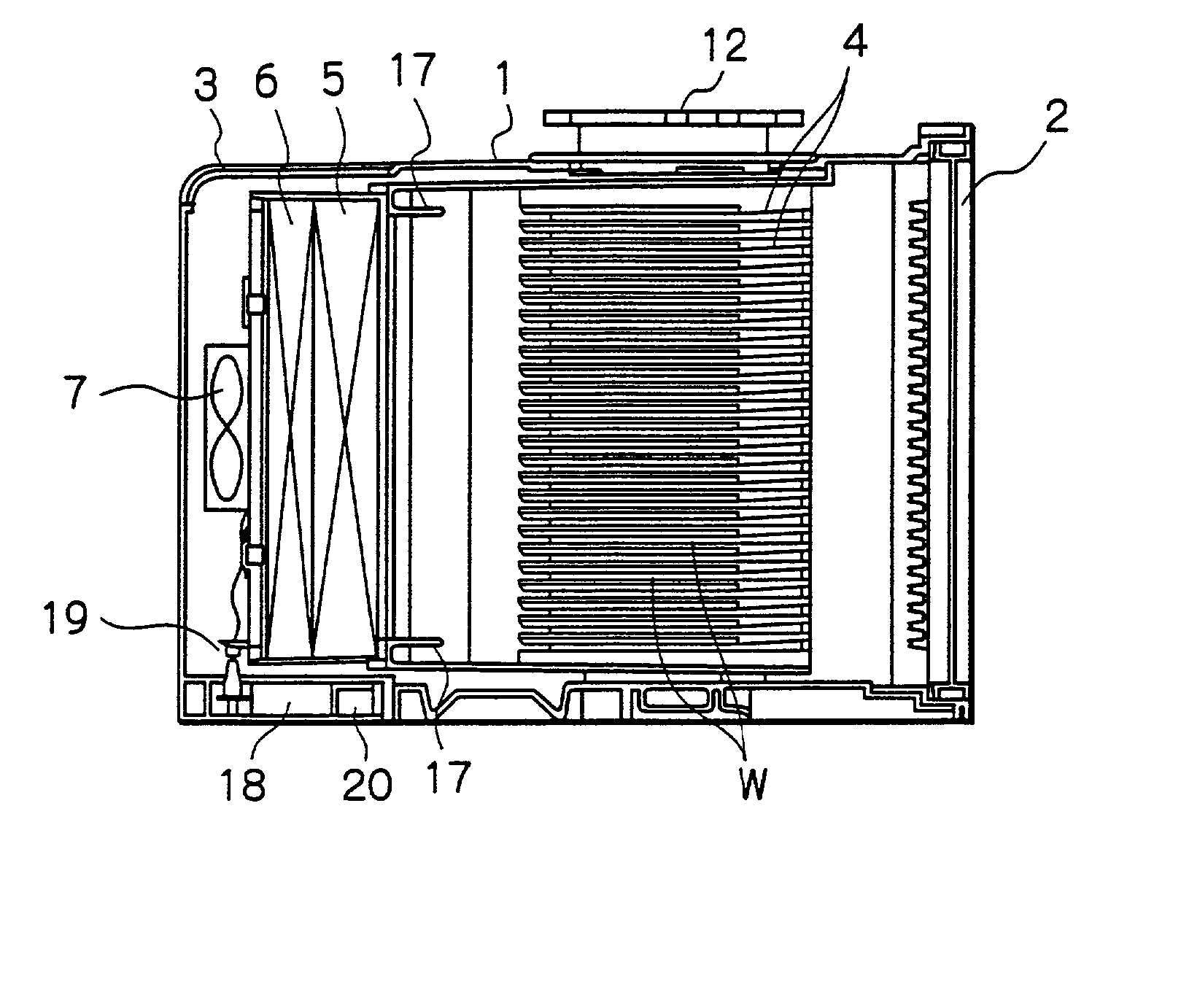
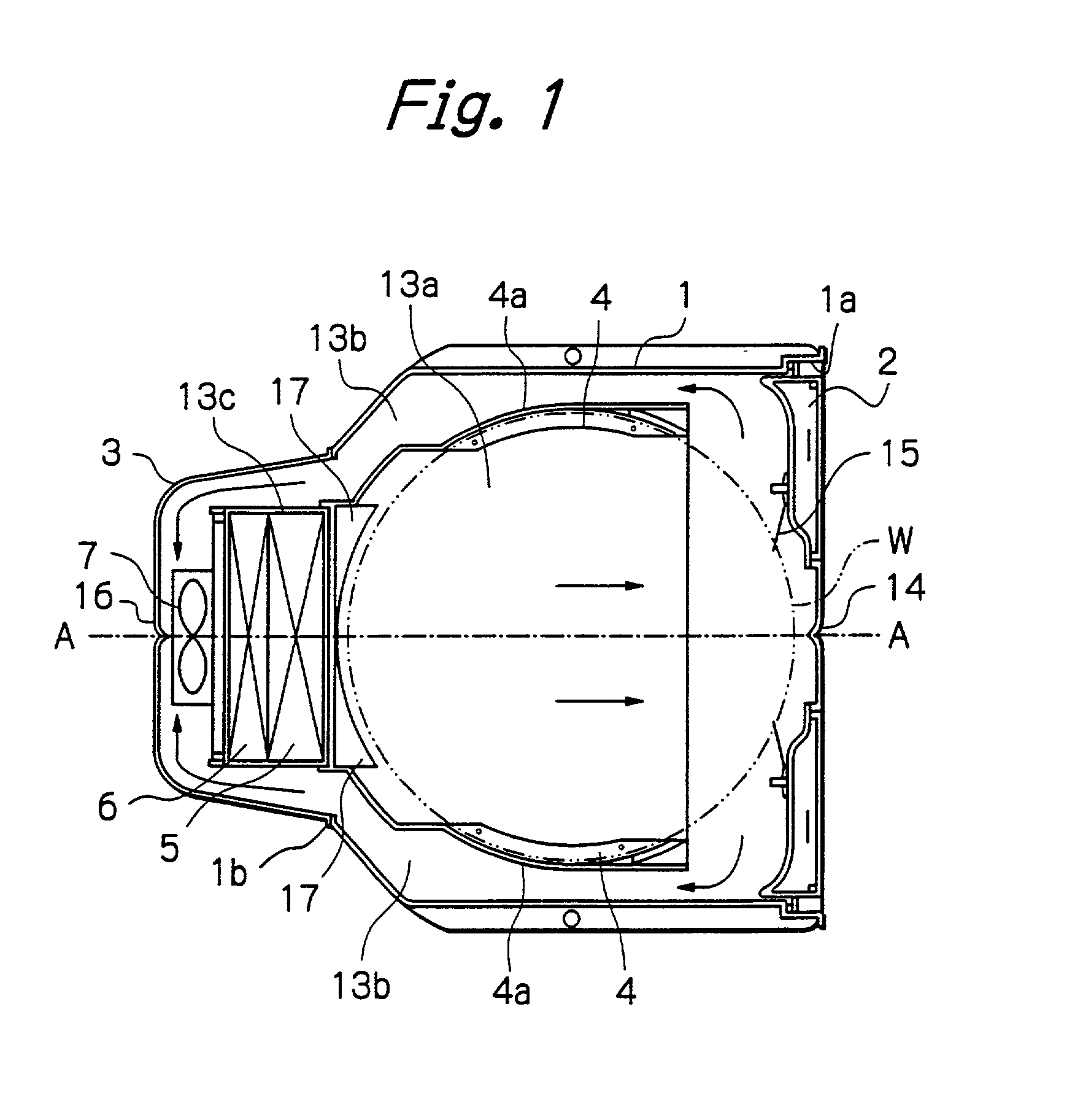
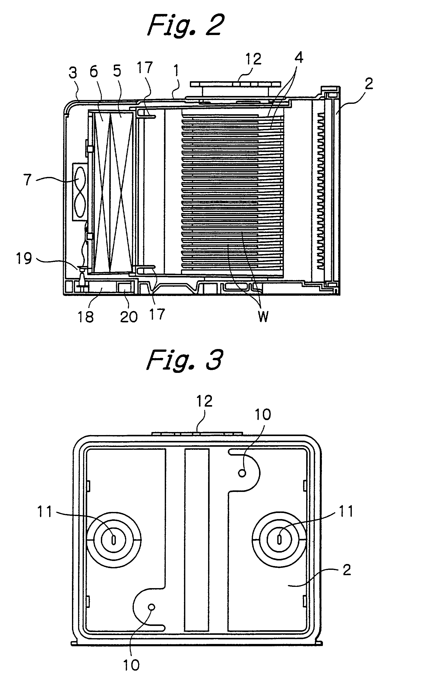
[0030] FIGS. 1 to 4 show an automation-compatible substrate transport container according to the present invention. In the substrate transport container, a plurality of 300-mm wafers (substrates to be treated) W are accommodated in groove-shaped pockets disposed in the inside of a container body to transport or store them. The substrate transport container has a cuboid container body 1 and a wafer loading / unloading door 2 adapted to be coupled to an automatic door opener (explained later) for automatically opening and closing the wafer loading / unloading door 2. The wafer loading / unloading door 2 is capable of mechanically opening and closing an opening 1a provided in a side of the container body 1. A cover 3 is located at a side of the container body 1 remote from the opening 1a to cover an opening 1b for insertion and withdrawal of filters and a fan motor stated below. The substrate transport container further has groove-shaped pockets 4 for carrying wafers W, a ULPA filter 5, a ch...

second embodiment

[0050] FIGS. 6 and 7 show the present invention. This embodiment differs from the first embodiment in that the size of wafers W is 200 millimeters, and a door 23 for automation interface is located in the bottom of the container 1. Wafers W that are accommodated in a wafer carrier 22 are put in the substrate transport container. In this embodiment, side walls 22a, 22b of the wafer carrier 22, which are integrated with the groove-shaped pocket 4' constitute the pair of partitions which separate the control chamber 13a and the side chambers 13b. Alternatively, a pair of partitions may be provided in the container box, and the wafer carrier 22 may be disposed between the partitions. The wafer carrier 22 may be received in and took out of the substrate transport container 1 together with closing and opening of the wafer loading / unloading door 2. The method of cleaning air in the substrate transport container is the same as in the first embodiment. It should be noted that in the second e...


PUM

PropertyMeasurementUnit
diameteraaaaaaaaaa
temperatureaaaaaaaaaa
diameteraaaaaaaaaa

Abstract

A substrate transport container having a carrier box including a container body and a door hermetically sealably covering an opening provided in the front of the container body. Partitions form a circulating flow path in the carrier box. The circulating flow path has a flow path in which air flows toward substrates and a flow path in which air flows toward a fan. A substrate carrying section is disposed in the flow path in which air flows toward the substrates to carry the substrates in such a way that the principal surfaces of the substrates are approximately parallel to the flow path in which air flows toward the substrates. A particle removing filter and a gaseous impurity trapping filter are placed on the upstream side of the substrate carrying section in the flow path in which air flows toward the substrates. A fan motor for driving the fan is incorporated in the carrier box to form an air current for circulating through the circulating flow path.

Description

BACKGROUND OF THE INVENTION[0001] The present invention relates to a substrate transport container suitable for use in storing or transporting objects, e.g. semiconductor wafers, photomasks, or hard disks, in an atmosphere of extremely high cleanliness.[0002] During transport or storage of substrates, e.g. semiconductor wafers or photomasks, produced in a semiconductor manufacturing factory, for example, if traces of dust or gaseous impurities present in the surrounding air adhere to the semiconductor wafers or other objects, the product yield is lowered. This tendency becomes increasingly remarkable as the degree of integration increases. In the field of magnetic disks also, recording has been becoming denser acceleratedly since the advent of magnetoresistive heads. Accordingly, there has been a demand for high cleanliness regarding not only dust but also gaseous impurities.[0003] To produce a clean space for accommodating substrates when transported or stored, a clean box and so f...

Claims


Application Information

Patent Timeline
Patent Type & Authority Applications(United States)
IPC IPC(8): B65D85/00B65G49/00H01L21/673
CPCH01L21/67393H01L21/67772B65D85/00
Inventor TANAKA, AKIRAOKUBO, KAZUOSUZUKI, YOKO
Owner EBARA CORP
Why Eureka
Try Eureka