Moving coil motor and implementations in MEMS based optical switches

a technology of moving coil and optical switch, which is applied in the direction of instruments, optical elements, propulsion systems, etc., can solve the problems of large static angular displacements that are difficult or impossible to achieve over a fixed duration, large electrical power or high voltage for a relatively small mirror displacement, and high heat build-up in the optical switch system. achieve the effect of small overall device footprint and large working surfa

Inactive Publication Date: 2002-09-19
INTEGRATED MICROMACHINES
View PDF10 Cites 55 Cited by
  • Summary
  • Abstract
  • Description
  • Claims
  • Application Information

AI Technical Summary

Benefits of technology

0017] In a further aspect of the present invention, the movable member of the moving coil motor is configured in more than one tier. In one embodiment, the moving coil motor is configured in two tiers, such that the working surface of the movable member is on a first tier and the drive coils are supported on a second tier. This configuration

Problems solved by technology

One of the inherent problems with prior art MEMS based scanning mirrors is that they require a relatively large amount of electrical power or high voltages for a relatively small mirror displacement.
Typically scanning mirrors operate at resonance frequency, and large static angular displacements are difficult or impossible to achieve over a fixed duration.
High power consumption leads to higher heat build-up

Method used


Image

  • Moving coil motor and implementations in MEMS based optical switches
  • Moving coil motor and implementations in MEMS based optical switches
  • Moving coil motor and implementations in MEMS based optical switches

Examples


Embodiment Construction

[0036] This invention is described below in reference to various embodiments and drawings. While this invention is described in terms of the best presently contemplated mode of carrying out the invention, it will be appreciated by those skilled in the art that variations and improvements may be accomplished in view of these teachings without deviating from the scope and spirit of the invention. This description is made for the purpose of illustrating the general principles of the invention and should not be taken in a limiting sense. The scope of the invention is best determined by reference to the appended claims.

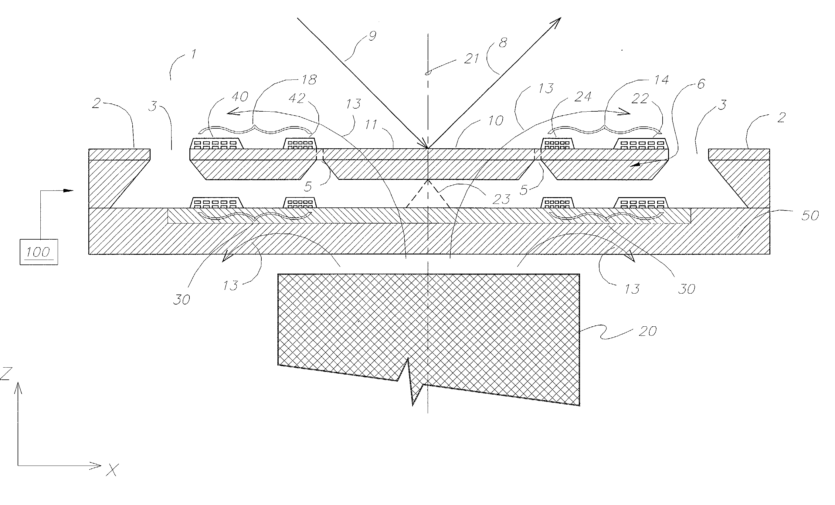
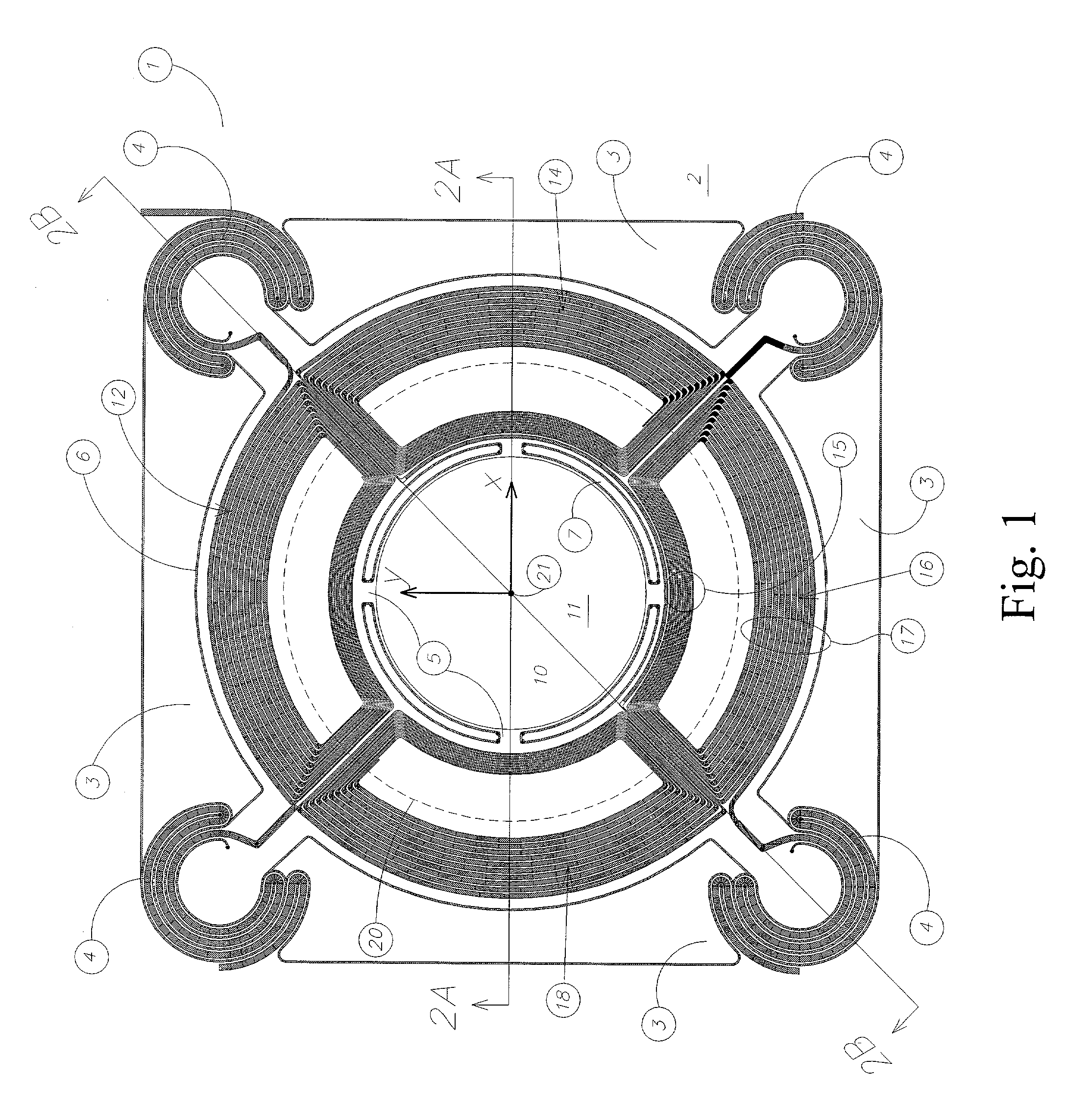
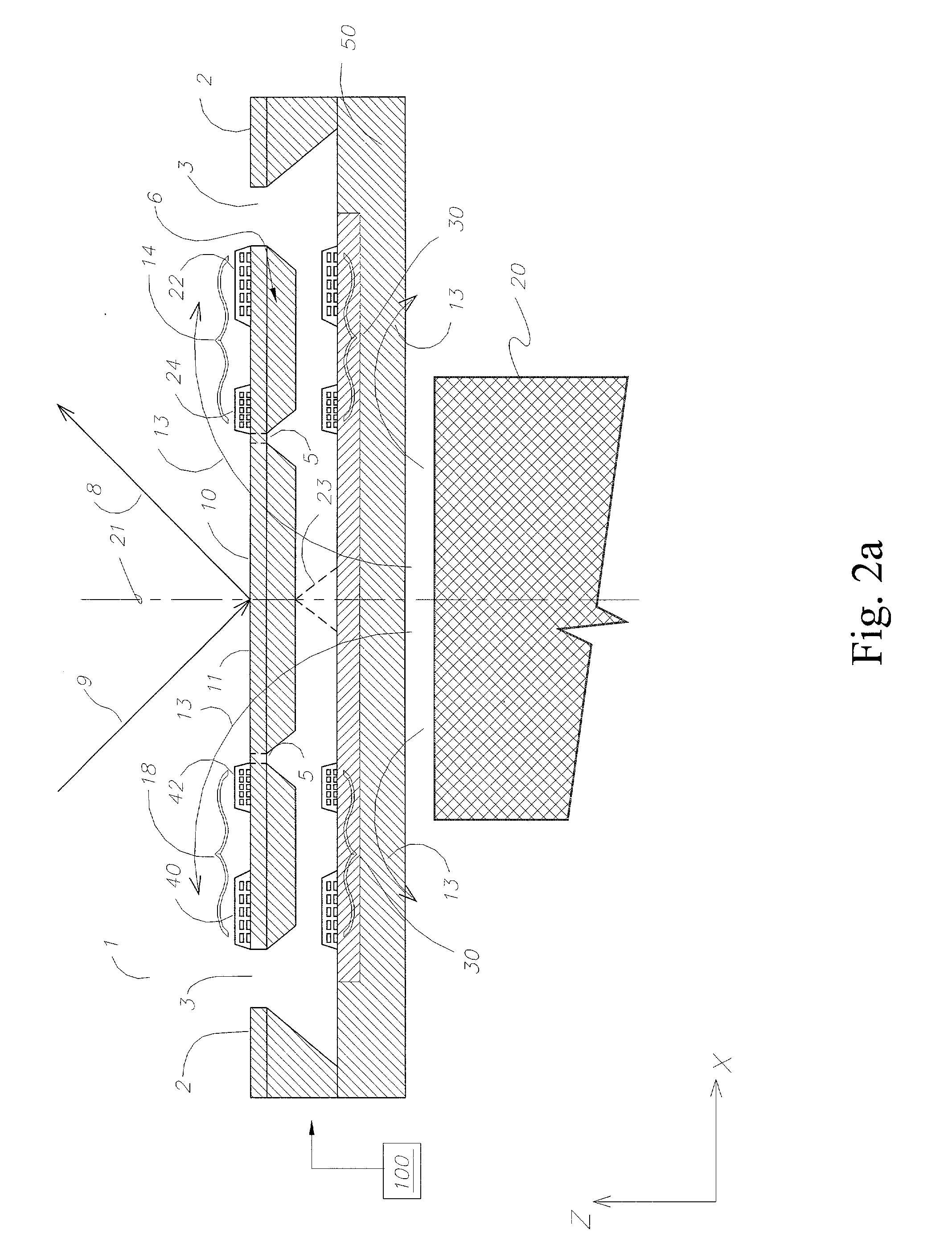
[0037] By way of illustration and not limitation of the inventive aspects of the moving coil motor of present invention, the present invention will be described below in reference to optical switches, and in particular with reference to optical switches in which a mirror is supported to move in at least two axes, in two or more degrees of freedom. The present invention is ...


PUM


Abstract

A moving coil motor has an axisymmetric magnetic field applied to the drive coils on the movable member of the motor. The movable member is suspended by springs. The moving coil motor may be configured in a MEMS format, with the movable member and its suspension springs fabricated from a mono-crystalline substance to improve structural integrity. MEMS based moving coil motors may be configured in an array. Sensors are provided to detect the relative spatial positions of the movable member. The movable member may include several tiers. In one application, the moving coil motor may be configured to support and drive a mirror surface on the movable member to form a galvanometer, optical switch, or other optical component. Singular moving coil motors may be configured in an optical cavity to facilitate the tuning of specific wavelengths while a number of moving coil motors may be configured to form an array of optical switches to facilitate switching in a multi-channel optical network.

Description

BACKGROUND OF THE INVENTION[0001] 1. Field of the Invention[0002] This invention relates to moving coil motors, and particularly to moving coil motors in the format of micro-electro-mechanical system ("MEMS").[0003] 2. Description of the Related Art[0004] MEMS includes micro-electro-mechanical devices that are fabricated by "micromachining", which involves carving a device out of a silicon wafer or other materials such as a slide of polymer or quartz, using topography based semiconductor manufacturing techniques (e.g., lithography, deposition, chemical and / or plasma etching, etc. processes). For example, moveable micromirrors may be implemented in the form of MEMS. One type of prior art MEMS based micromirrors use Lorentz forces to generate a torque to scan or oscillate the mirror. The mirror is pivotally supported by torsion bars along the rotation axis. A common use for such MEMS mirror devices is a galvanometer or optical scanning unit commonly used in storage and imaging technol...

Claims


Application Information

Patent Timeline
IPC IPC(8): G02B6/35H02K26/00
CPCG02B6/3518G02B6/3556G02B6/3572H02K26/00H02K2201/18
Inventor TEMESVARY, VIKTORIA A.ISMAIL, SALLEHWU, SHUYUN
Owner INTEGRATED MICROMACHINES
Why Eureka
Try Eureka