Apparatus for forming hydrogen

a technology of apparatus and hydrogen, which is applied in the direction of metal/metal-oxide/metal-hydroxide catalysts, chemical/physical/physical-chemical stationary reactors, and hydrogen fuel infrastructures, etc., can solve the problems of large co reduction, catalyst activity deterioration, and inability to large-scale co reduction, etc., to reduce the high concentration of carbon monoxide, reduce the effect of exothermic activity and catalytic activity of oxidation reaction

Inactive Publication Date: 2003-01-02
PANASONIC CORP
View PDF1 Cites 17 Cited by
  • Summary
  • Abstract
  • Description
  • Claims
  • Application Information

AI Technical Summary

Benefits of technology

[0057] Therefore, the present invention uses the Pt catalyst and the Ru catalyst for the purifying section. In the Pt catalyst, the catalytic activity deteriorates at low temperatures with increase of carbon monoxide concentration. On the other hand, the Ru catalyst is active for oxidation reaction of carbon monoxide even at relatively low temperatures. Thus, when the Pt catalyst and the Ru catalyst are combined, the Ru catalyst causes carbon monoxide to react to some extent and the amount of carbon monoxide adsorbed on the Pt catalyst is therefore reduced, so that the catalytic activity for oxidation reaction of carbon monoxide is retained. This makes it possible to decrease a high concentration of carbon monoxide even at relatively low temperatures in comparison with the use of only the Pt catalyst. When the catalyst temperature is high, on the other hand, the oxidation reaction of carbon monoxide by the Pt catalyst is more likely to occur so that the methanation reaction by the Ru catalyst is less likely to occur. When the methanation reaction and the oxidation reaction of carbon monoxide are compared, the oxidation reaction of carbon monoxide is less exothermic; therefore, it is possible to suppress heat generation over the catalyst and thereby prevent the vicious circle that the increase of the catalyst temperature causes the methanation reaction to proceed.
[0058] As described above, the hydrogen producing apparatus of the present invention enables reduction of carbon monoxide even at relatively low temperatures; thus, even if oxygen is supplied in an amount suitable for oxidation of a high concentration of carbon monoxide, the catalyst temperature does not become high eventually, so that it is possible to decrease carbon monoxide.
[0063] In consideration of the reactivity at low temperatures and high temperatures, the number of Ru atoms of the purifying catalyst including Pt and Ru is desirably set in a range of not less than one tenth and not more than 1 of the number of Pt atoms. Also, the use of the catalyst comprising a Pt--Ru alloy allows the catalyst operating temperature range to become wider, making it possible to successfully deal with a high concentration of carbon monoxide. In the use of the Pt--Ru alloy, where Pt and Ru catalysts exist in closer vicinity, carbon monoxide is consumed more effectively over the Ru catalyst and the activity of the Pt catalyst is therefore more likely to be retained at low temperatures. At high temperatures, the methanation reactions are suppressed more effectively than in the use of the catalyst composed of only Ru.
[0064] Further, combination of the Rh catalyst and the Pt catalyst also produces the same effects as the Ru catalyst. This is because the Rh catalyst is also active for oxidation reaction of carbon monoxide even at low temperatures.

Problems solved by technology

Fuel infrastructure for hydrogen, however, has not yet been built up and the hydrogen therefore needs to be produced on a site where the cell is installed.
Since the Fe--Cr based catalyst is used at high temperatures, large reduction of CO is not possible.
However, in the case of intermittent operations in which the apparatus is started and stopped repeatedly or in other cases, air gets into the shifting section to oxidize the catalyst, so that the activity of the catalyst deteriorates significantly.
Further, the problem of catalyst activity deterioration arises also when the catalyst is used at high temperatures not lower than 300.degree. C. and in other cases.
However, in comparison with the Cu--Zn based catalyst, the reactivity at low temperatures may deteriorate slightly.
This deterioration increases the CO concentration at the outlet of the shifting section and produces a problem that the conventional Pt or Ru based catalyst of the purifying section is unable to decrease the CO sufficiently.
In the conventional heating method in which the heat of the reformed gas released from the reforming section is utilized to heat the shifting section, it takes a long time for the catalyst temperature to become stable in correspondence with the thermal capacity of each reaction section.
A hindrance to this temperature stabilization is condensation of water in the gas which takes place at low temperature parts of the gas flow route during the heating operation.
This causes the gas released from the reforming section to contain a considerable amount of steam.
Also, when the apparatus is started from room temperature, in the shifting section and other parts that are heated by the heat contained in the reformed gas, condensation of excessive steam in the reformed gas takes place.
This condensation of water gives rise to following problems.
The first problem is that the temperature will not rise at a part where condensation has took place until condensed water evaporates again.
However, heat is exchanged promptly between the gaseous steam and, for example, the walls of the apparatus, to cause condensation of water, but heat exchange between the liquid and, for example, the walls of the apparatus becomes a rate-determining step in evaporating the condensed water, thereby making the evaporation speed slow.
As a result, it takes a longer time to heat the shift catalyst up to an optimal reaction temperature, making the start-up time longer.
Thus, reduction of the start-up time becomes a large problem with respect to apparatus operation in the apparatus to be subjected to frequent starts and stops.
The second is that the condensed water causes the catalytic activity of the shift catalyst to deteriorate.
When condensation of water takes place, however, the catalyst is oxidized by the water, so that the catalytic activity deteriorates remarkably.
Thus, frequent starts and stops will cause the catalytic activity to deteriorate significantly, resulting in an increase in the CO concentration of the shifted gas.
Particularly in an application as a hydrogen producing apparatus for supplying hydrogen to a solid polymer electrolyte fuel cell, the increase of CO impairs the power generating characteristics significantly, presenting a serious problem.
On the other hand, fuel cells having a small power generating capacity, intended for home use or the like, are assumed to be subjected to frequent starts and stops of the apparatus.
Also, when condensation of water takes place over the shift catalyst, the catalyst is oxidized and the shift reaction of water and CO is thereby impeded.
This is one of the causes of the deterioration of the properties of the shift catalyst in the hydrogen producing apparatus with a large number of starts and stops of the apparatus.
Especially in the Cu--Zn catalyst, which is highly active while in a reduced state, the reactivity is markedly deteriorated by the oxidation of the catalyst by water.

Method used


Image

  • Apparatus for forming hydrogen
  • Apparatus for forming hydrogen
  • Apparatus for forming hydrogen

Examples


embodiment 1

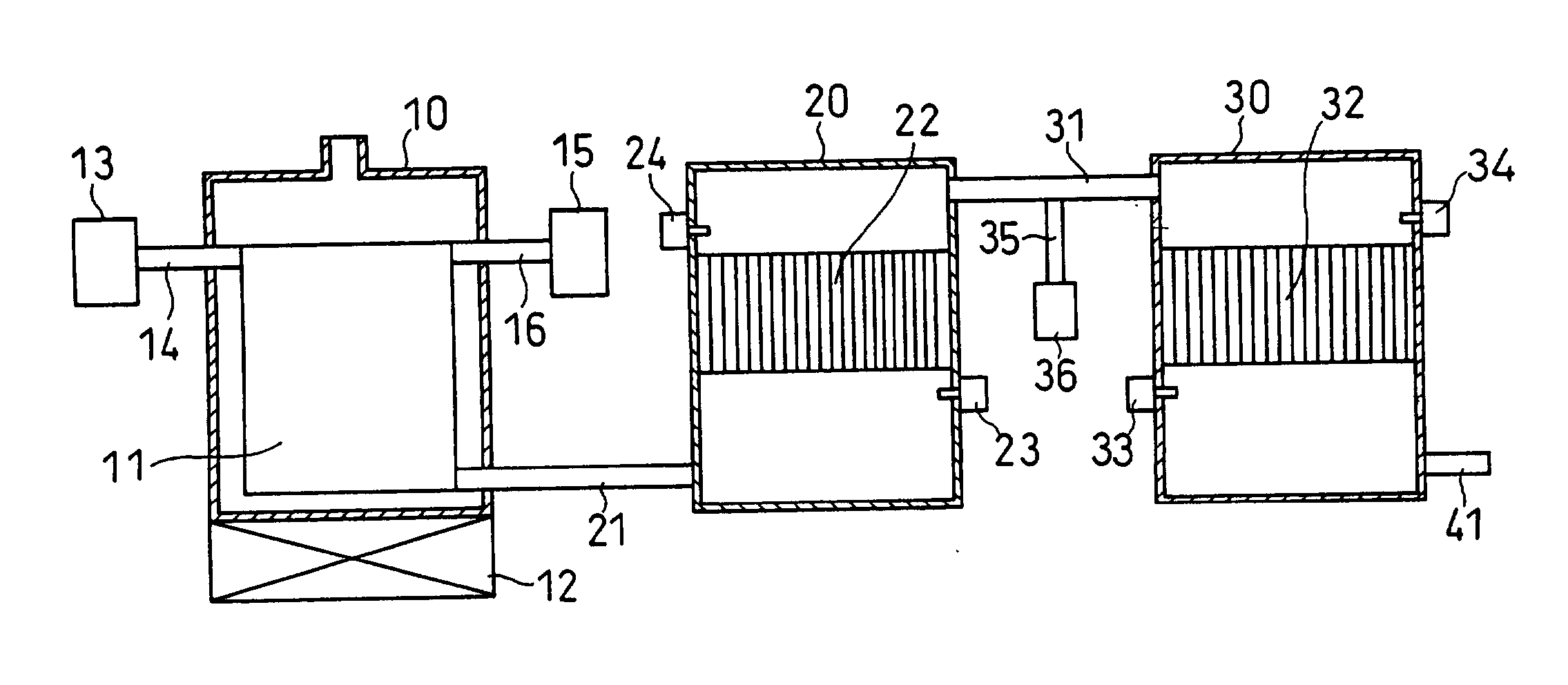
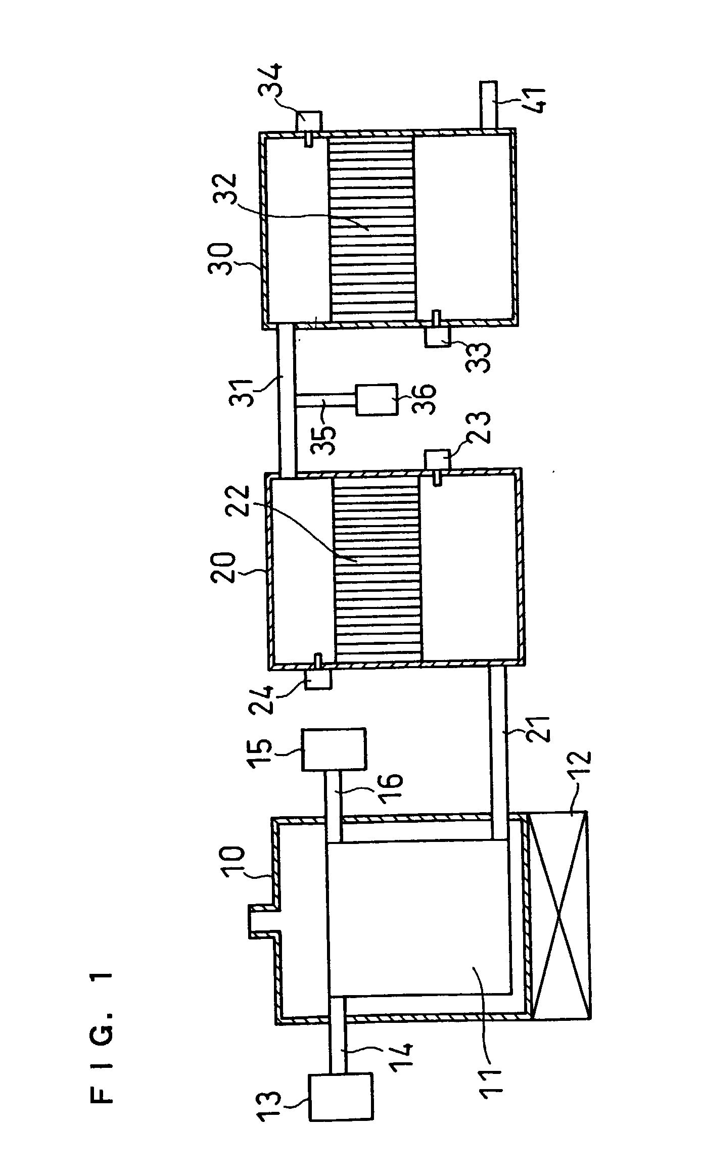
[0066] The following will describe an example of the operation of the hydrogen producing apparatus of

[0067] Methane gas was used as the feedstock, and 1 mol of methane gas was added with 2.5 mol of water and was steam reformed. The resultant outlet gas in the reforming section 10 was a hydrogen gas containing about 10% of carbon monoxide and about 10% of carbon dioxide. When this hydrogen producing apparatus was operated in a steady manner, the carbon monoxide concentration of the outlet gas of the shifting section 20 was about 1%. At this time, the temperatures of the shift catalyst upstream and downstream of the hydrogen gas flow were detected by the first temperature detector 23 and the second temperature detector 24 to examine if the shifting section was kept at a temperature capable of decreasing carbon monoxide effectively.

[0068] Air was added to this hydrogen gas from the air supply section 36 such that the amount of oxygen contained in the air became four times the amount of...

embodiment 2

[0072] Embodiment 2

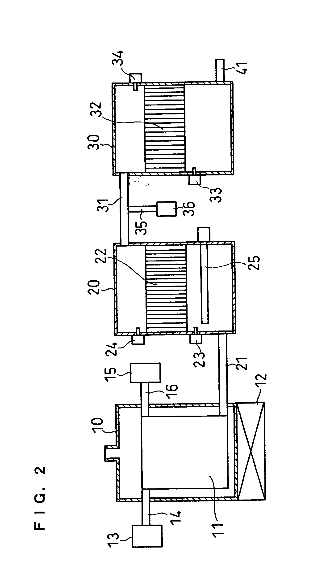
[0073] FIG. 2 shows the constitution of a hydrogen producing apparatus of this embodiment.

[0074] The difference from FIG. 1 is that a heater 25 is provided as heating means in the shifting section 20. The heater 25, which is, for example, an electric heater, minimizes condensation of water especially in the shifting section when the apparatus is started, shortens the start-up time, and allows the activity of the shift catalyst to be maintained.

[0075] The dew point of the reformed gas can be calculated on the basis of the amounts of the feedstock and water supplied. For example, when the feedstock is methane and water is supplied in an amount three times the number of moles of the methane, provided that 100% of the methane is steam reformed into carbon dioxide and hydrogen, the steam partial pressure of the gas after the reforming reaction becomes one sixth from the reaction formula. Thus, the dew point of the gas can be easily calculated.

[0076] According to the pr...

embodiment 3

[0077] Embodiment 3

[0078] FIG. 3 shows the constitution of a hydrogen producing apparatus of this embodiment. The apparatus has almost the same constitution as that of Embodiment 2 except that the heater 25 is removed from the shifting section and an air supply section 26 is connected to the gas conduit 21 through a gas conduit 27.

[0079] In this embodiment, the air supply section 26 supplies air to the reformed gas to heat the shifting section and the shift catalyst. Also, in the use of the shift catalyst of the present invention, oxygen in the supplied air oxidizes part of the reformed gas component readily, and heat is generated upon the oxidation to heat the shifting section and the shift catalyst.

[0080] Accordingly, in the same manner as in Embodiment 2, this embodiment makes it possible to heat the shifting section to prevent water condensation in the shifting section, to shorten the start-up time of the apparatus, and to prevent deterioration of the properties of the shift cat...


PUM

PropertyMeasurementUnit
temperatureaaaaaaaaaa
temperaturesaaaaaaaaaa

Abstract

A hydrogen producing apparatus comprising: a reforming section having a reforming catalyst which causes a reaction between a carbon-containing organic compound as a feedstock and water; a feedstock supply section for supplying the feedstock to the reforming section; a water supply section for supplying water to the reforming section; a heating section for heating the reforming catalyst; a shifting section having a shift catalyst which causes a shift reaction between carbon monoxide and water contained in a reformed gas supplied from the reforming section; and a purifying section having a purifying catalyst which causes oxidation or methanation of carbon monoxide contained in a gas supplied from the shifting section, wherein the shift catalyst comprises a platinum group metal and a metal oxide.

Description

[0001] The present invention relates to a hydrogen producing apparatus for supplying hydrogen to fuel cells or the like.[0002] Cogeneration systems using a fuel cell having high power-generation efficiency are receiving special attention as decentralized power generation systems capable of effective utilization of energy. Many of the fuel cells, for example, phosphoric acid fuel cells currently commercially available and polymer electrolyte fuel cells currently under development, use hydrogen as a feedstock to generate electric power. Fuel infrastructure for hydrogen, however, has not yet been built up and the hydrogen therefore needs to be produced on a site where the cell is installed. Methods for producing the hydrogen includes a steam reforming method and an auto-thermal method. In the methods, a carbon-containing organic compound as the feedstock, for example, natural gas, hydrocarbon such as LPG, alcohol such as methanol, naphtha or the like is reacted with water in a reformin...

Claims


Application Information

Patent Timeline
Patent Type & Authority Applications(United States)
IPC IPC(8): B01J8/04B01J19/24B01J23/40B01J23/63B01J23/72B01J35/00C01B3/16C01B3/48C01B3/58C10K3/04H01M8/06
CPCB01J8/0453B01J8/0457B01J8/0488B01J8/0496B01J19/2485B01J23/40B01J23/63B01J23/72B01J35/0006B01J2208/00061B01J2208/00194B01J2208/00504B01J2208/00716B01J2219/0004B01J2219/00198B01J2219/002B01J2219/00202B01J2219/00213B01J2219/00231C01B3/16C01B3/48C01B3/583C01B3/586C01B2203/0233C01B2203/0283C01B2203/0288C01B2203/044C01B2203/0445C01B2203/047C01B2203/066C01B2203/0811C01B2203/0816C01B2203/085C01B2203/0866C01B2203/0877C01B2203/0883C01B2203/0894C01B2203/1023C01B2203/1041C01B2203/1064C01B2203/107C01B2203/1076C01B2203/1082C01B2203/1223C01B2203/1241C01B2203/1247C01B2203/1604C01B2203/1609C01B2203/1619C01B2203/1661C01B2203/169C01B2203/1695C01B2203/82C10K3/04H01M8/0631Y02E60/50Y02P20/52C01B3/38
Inventor TAGUCHI, KIYOSHITOMIZAWA, TAKESHIUKAI, KUNIHIROSHONO, TOSHIYUKIKITAGAWA, KOICHIROUEDA, TETSUYAFUJIHARA, SEIJIYOSHIDA, YUTAKA
Owner PANASONIC CORP
Why Eureka
Try Eureka