
Method for measuring concentrations of gases and vapors using controlled flames

Inactive Publication Date: 2003-01-02
GAS TECH INST
View PDF6 Cites 15 Cited by
  • Summary
  • Abstract
  • Description
  • Claims
  • Application Information

AI Technical Summary

Benefits of technology

[0016] Advantages of using controlled flames as a means for monitoring combustion emissions include the ability to operate reliably and continuously for extended periods of time in harsh industrial environments and simultaneous measurement of oxygen, carbon monoxide, total hydrocarbons and even NO.sub.x. In addition, the presence of contaminants including dust, halides, NO.sub.x and SO.sub.x does not impair operation and the equipment required to carry out the method is simple, inexpensive and does not require continuous calibration. Yet a further advantage of the method and apparatus of this invention is the range of gas mixtures that can be analyzed for oxygen concentration. Measuring the oxygen concentration of "dirty", hot gases such as exhaust gases from industrial combustion processes using conventional means is difficult. This invention provides a means for determining oxygen concentrations of these difficult gas mixtures and for measuring oxygen concentration in other static and flowing gas mixtures at less stringent conditions.
[0017] Finally, this invention offers significant advantages to the operators of industrial combustion processes because the oxygen concentration data from the dirty, hot exhaust gases immediately downstream of a furnace provides direct information regarding the combustion process. The data available from conventional systems only provide indirect information about the combustion process. The immediate availability of the oxygen concentration in the dirty, hot exhaust gases enables the combustion process control system and operators to optimize the combustion process in real time.

Problems solved by technology

However, due to their cost, the inherent time delay in obtaining the results and their unreliability in harsh industrial environments, which typically include a combination of heat, corrosive gases, dust and the like, none of these methods is rugged, low-cost or reliable enough to provide input to combustion control systems.
While this technique is accurate and reliable, disadvantages of these instruments include the need for regular calibration and a response time that is too slow for control applications.
In practice, exhaust gas samples must be cooled and dried before being sent to the analyzer, which results in significant time delays.
While response time is rapid, these analyzers have several disadvantages including high labor maintenance costs, the use of expensive materials required to make the sensors, and a short service life of only six to 12 months in harsh environments.
A serious disadvantage of traditional continuous emissions monitors is a substantial time delay between the moment of combustion and when the results of the analysis are complete because the sample must be extracted from the flue gas stream, dried and finally analyzed.
This makes the implementation of continuous emissions monitors for burner control very difficult.
This technique has a number of serious problems and limitations in industrial practice.
System calibration is difficult, and there is typically strong interference from refractory or wall radiation.
In addition, the radiation spectrum coming from real, industrial scale, flames often is estimated as black body radiation spectrum making separate radiation intensity measurements associated with detectable radicals difficult.
Notwithstanding the number of known methods and devices for analyzing the content of a gaseous mixture, none of them provide real-time analysis whereby the results may be employed to control an application, such as a combustion process.
In addition, known methods and devices do not simultaneously measure oxygen concentration and the concentrations of other gases, including CO, total hydrocarbons, NO.sub.x and the like in static and flowing gases, including harsh industrial exhaust gas streams.
Conventional oxygen sensors and methods for determining oxygen concentration in a gaseous stream do not have these capabilities.
Measuring the oxygen concentration of "dirty", hot gases such as exhaust gases from industrial combustion processes using conventional means is difficult.

Method used


Image

  • Method for measuring concentrations of gases and vapors using controlled flames
  • Method for measuring concentrations of gases and vapors using controlled flames
  • Method for measuring concentrations of gases and vapors using controlled flames

Examples


Embodiment Construction

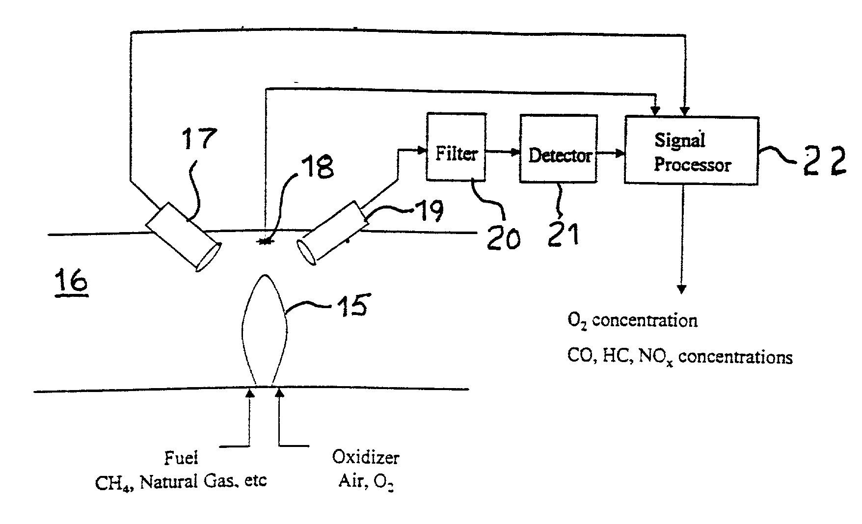
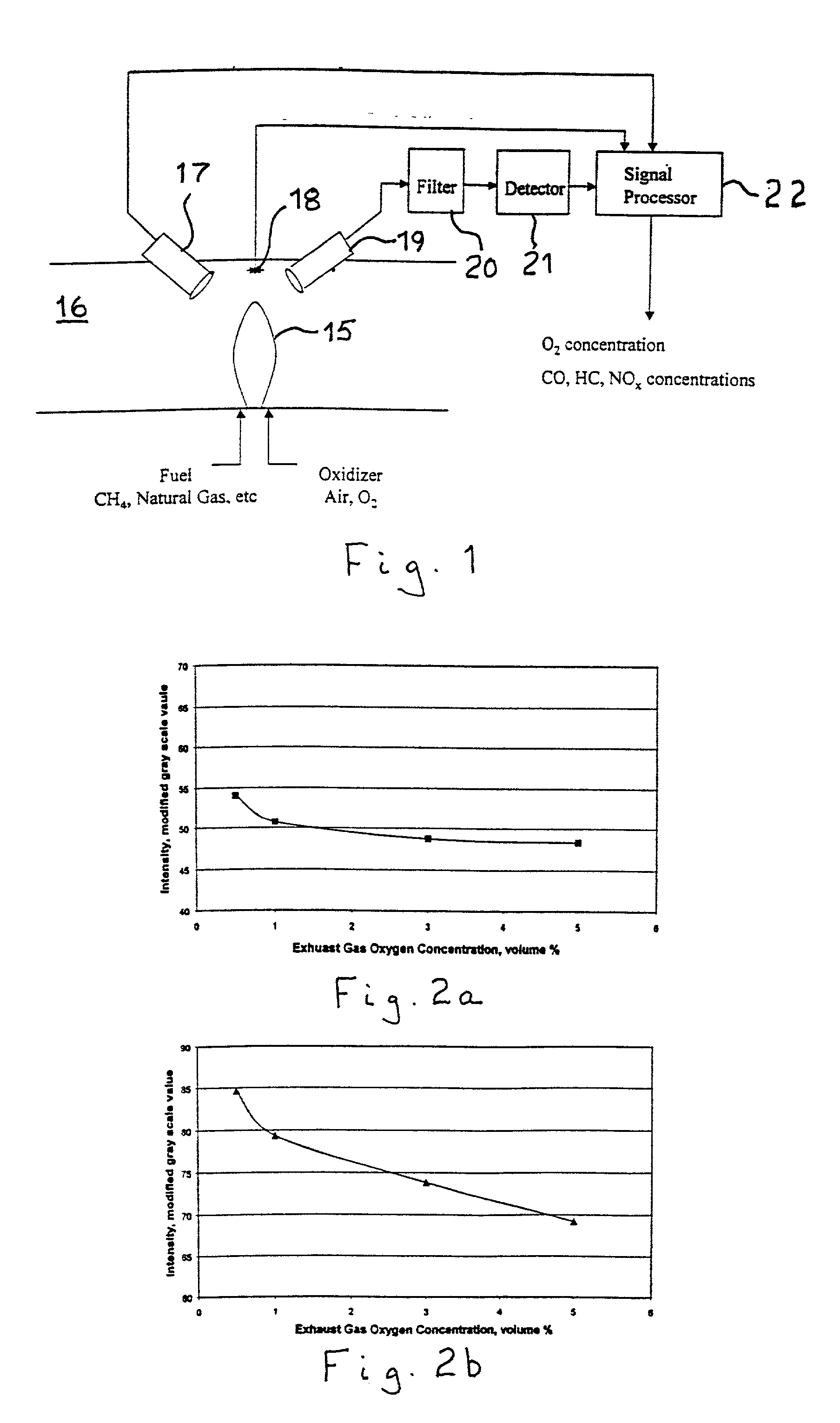
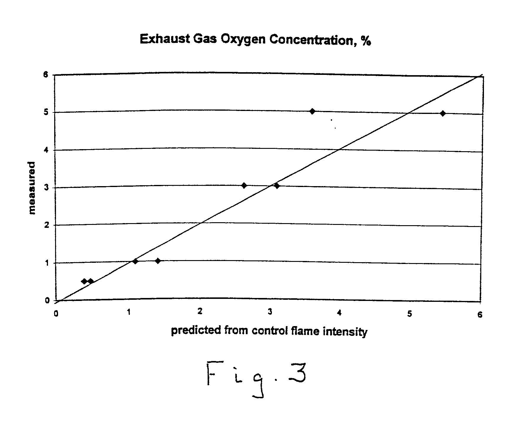
[0023] The concentrations of oxygen and other gases and vapors in a gas mixture in accordance with the method of this invention are determined by making optical measurements of narrow spectral bands in a controlled sensor flame placed in the gas mixture. As used herein, the term "narrow spectral band" refers to light wavelength ranges of less than about 20 nanometers, and preferably less than 10 nanometers, in width. The observed optical bands correspond to excited energy levels of various radical species including, but not limited to, O--H, C--H, and C--C, that are located in the ultraviolet and visible regions of the spectrum. Measurements of other characteristics of the controlled sensor flame, including temperature near or in the flame, flame length, flame shape, etc. may also be made along with the intensities of narrow spectral band optical readings to assist in determining oxygen concentrations. The information collected from the controlled sensor flame is input to software t...


PUM


Abstract

A method and apparatus for measuring the concentration of at least one gaseous component and / or vaporous component of a gaseous mixture in which a controlled sensor flame is introduced into the gaseous mixture and at least one narrow spectral band in the controlled sensor flame is optically measured. The concentration of the gaseous component using a result obtained from the optical measuring of the at least one narrow spectral band is then calculated. The method of this invention is particularly suitable for substantially real-time control of combustion processes.

Description

[0001] 1. Field of the Invention[0002] This invention relates to a method for measuring the concentration of gases and vapors in a gaseous mixture. More particularly, this invention relates to a method for measuring the concentration of oxygen in a gaseous mixture. This invention is particularly useful for measuring oxygen concentration in hot, dirty exhaust gases from combustion processes. In addition, this invention provides a means for real-time control of combustion processes based upon the concentration of oxygen or combustion-derived gases or other gases and vapors in the exhaust gases of the combustion processes.[0003] 2. Description of Prior Art[0004] There are three basic methods for measuring the concentration of oxygen in a gas mixture in commercial use. However, due to their cost, the inherent time delay in obtaining the results and their unreliability in harsh industrial environments, which typically include a combination of heat, corrosive gases, dust and the like, non...

Claims


Application Information

Patent Timeline
IPC IPC(8): G01N21/72
CPCG01N21/72Y10T436/21Y10T436/178459Y10T436/218Y10T436/177692Y10T436/208339Y10T436/204998Y10T436/207497Y10T436/205831Y10T436/179228
Inventor ABBASI, HAMID A.RUE, DAVID M.
Owner GAS TECH INST
Learn More