Electro-optic display and lamination adhesive

a technology of optical display and adhesive composition, applied in the direction of adhesive types, identification means, instruments, etc., can solve the problems of preventing their widespread use, imposing stringent requirements on the adhesive, and inadequate service life of these displays, so as to achieve economic manufacture of the display

Inactive Publication Date: 2003-02-06
E INK CORPORATION
View PDF99 Cites 262 Cited by
  • Summary
  • Abstract
  • Description
  • Claims
  • Application Information

AI Technical Summary

Benefits of technology

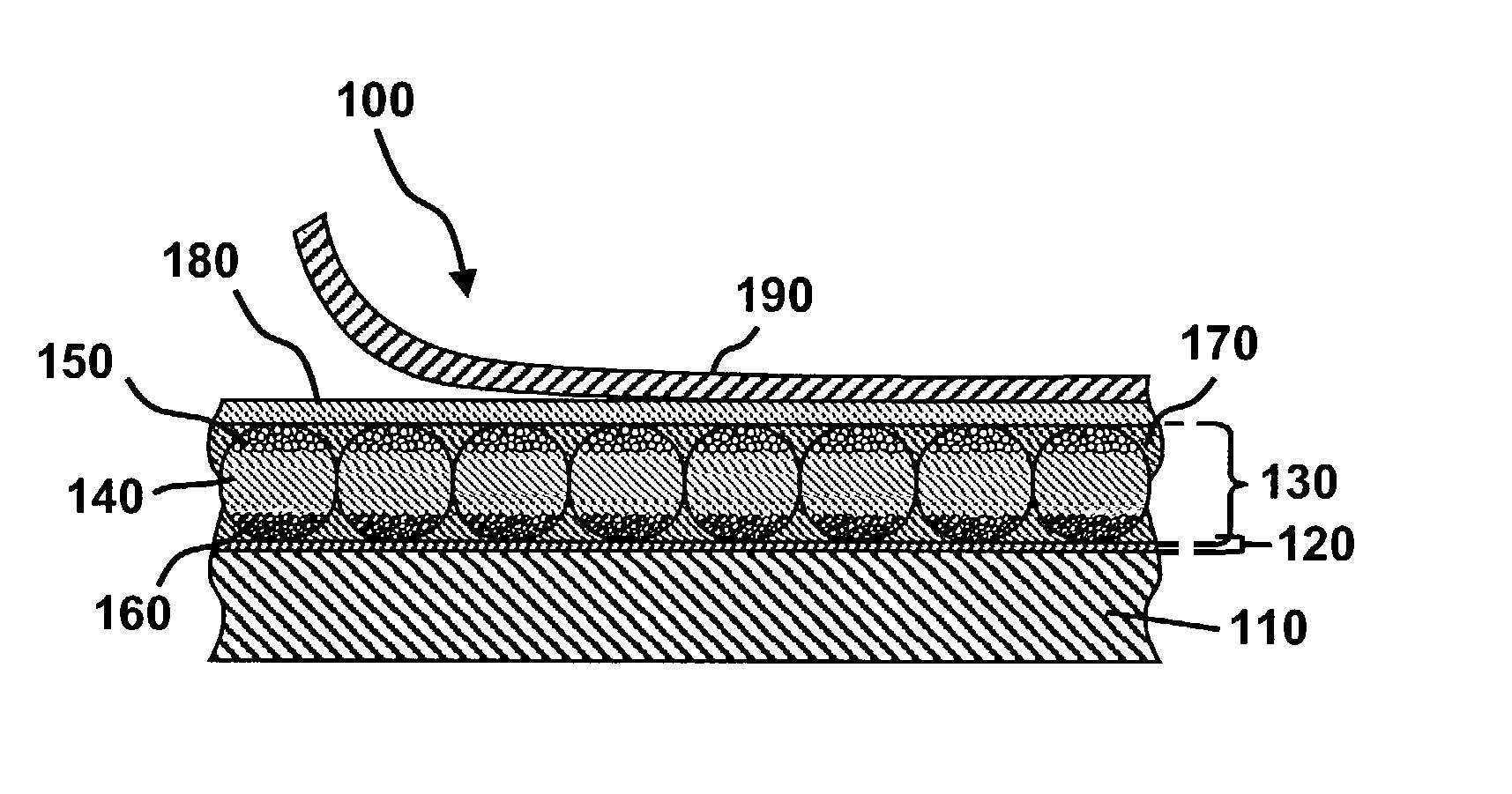
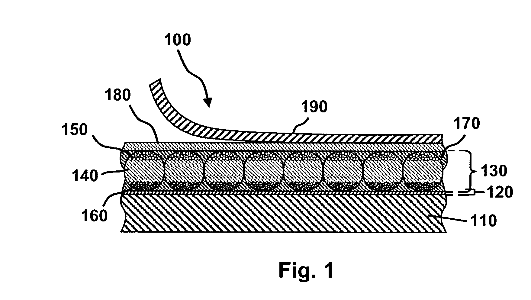
0117] Using a lamination adhesive with volume resistivity (and preferably other properties) which are stable upon long term storage also assists in ensuring economical manufacture of the display. As already discussed, for commercial reasons, it is convenient to prepare a front plane laminate of the form shown in FIG. 1 comprising a substrate, a conductive layer, an electro-optic layer, a lamination adhesive and a release sheet; this front plane laminate may be prepared in large batches, preferably using a

Problems solved by technology

Nevertheless, problems with the long-term image quality of these displays have prevented their widespread usage.
For example, particles that make up electrophoretic displays tend to settle, resulting in inadequate service-life for these displays.
However, vacuum lamination of the two parts of an electro-optic display in this manner imposes stringent requirements upon the lamination adhesive used, especially in the case of a display using an encapsulated electrophoretic medium.
The lamination adhesive must have adequate flow properties at the lamination temperature to ensure high quality lamination, and in this regard, the demands of laminating encapsulated electrophoretic and some other types of electro-optic media are unusually difficult; the lamination has be conducted at a temperature of not more than about 110.degree. C. since the medium cannot be exposed to substantially higher temperatures without damage, but the flow of the adhesive must cope with the relatively uneven surface of the capsule-containing layer, the surface of which is rendered irregular by the underlying capsules.
The lamination temperature should indeed be kept as low as possible, and room temperature lamination would be ideal, but no commercial adhesive has been found which permits such room temperature lamination.
It has also been found that a lamination adhesive used in an electro-optic display must meet a variety of electrical criteria, and this introduces considerable problems in the selection of the lamination adhesive.
However, in such applications, the electrical properties of the lamination adhesive are not relevant, and consequently the commercial manufacturers pay no heed to such electrical properties.
If the resistivity of the adhesive layer is too high, a substantial voltage drop will occur within the adhesive layer, requiring an increase in voltage across the electrodes.
Increasing the voltage across the electrodes in this manner is undesirable, since it increases the power consumption of the display, and may require the use of more complex an

Method used


Image

  • Electro-optic display and lamination adhesive
  • Electro-optic display and lamination adhesive
  • Electro-optic display and lamination adhesive

Examples


example 2

[0122] This Example illustrates the improved stability of the volume resistivity and dielectric constant of the aforementioned R 9320 upon prolonged storage provided by blending the material with the aforementioned R 9000.

[0123] Example 1 was repeated, except that R 9000 was substituted for U KA 8713, that the storage period was 4000 hours, and that the volume resistivity measurements were supplemented by measurements of the dielectric constant of the blends using the same impedance spectrometer as previously mentioned. The volume resistivity results are shown in FIG. 3 of the accompanying drawings and the dielectric constant results in FIG. 4.

[0124] From FIG. 3, it will be seen that, although the volume resistivities of both R 9320 and R 9000 underwent substantial changes over the test period, the blends had much more stable resistivities. In particular, the performance of the 50 / 50 w / w blend was outstanding, displaying a variation by less than a factor of 2 throughout the storage ...

example 3

[0125] This Example illustrates the improved stability of the volume resistivity and dielectric constant of the aforementioned R 9320 upon prolonged storage provided by blending the material with the aforementioned U 53. (U 53 is sold as an adhesive but has been found to give insufficient adhesive strength when used in the type of electrophoretic display used in these experiments.)

[0126] Example 2 was repeated, except that the aforementioned U 53 was substituted for the R 9000 and that the storage period was 6000 hours. The volume resistivity results are shown in FIG. 5 of the accompanying drawings and the dielectric constant results in FIG. 6.

[0127] From FIG. 5, it will be seen that the substantial changes in the volume resistivities of R 9320 over the test period were much less pronounced in the blends. In particular, the resistivities of the 75 / 25 and 50 / 50 w / w blends were within the acceptable range throughout the storage period. Similarly, FIG. 6 shows that both the 75 / 25 and 5...

example 4

[0128] This Example illustrates the improved stability of the volume resistivity and dielectric constant of the aforementioned R 9320 upon prolonged storage provided by blending the material with the aforementioned U 54. (U 54 is sold as an adhesive but has been found to give insufficient adhesive strength when used in the type of electrophoretic display used in these experiments.)

[0129] Example 2 was repeated, except that the aforementioned U 54 was substituted for the R 9000 and that the storage period was 5500 hours. The volume resistivity results are shown in FIG. 7 of the accompanying drawings and the dielectric constant results in FIG. 8.

[0130] From FIG. 7, it will be seen that the substantial changes in the volume resistivities of R 9320 over the test period were much less pronounced in the blends. In particular, the resistivities of the 75 / 25 and 50 / 50 w / w blends were within the acceptable range throughout the storage period. Similarly, FIG. 8 shows that both the 75 / 25 and 5...


PUM

PropertyMeasurementUnit
Temperatureaaaaaaaaaa
Fractionaaaaaaaaaa

Abstract

An electro-optic display comprises first and second substrates and a lamination adhesive layer and a layer of a solid electro-optic material disposed between the first and second substrates, the lamination adhesive layer having a volume resistivity, measured at 10° C., which does not change by a factor of more than about 3 after being held at 25° C. and 45 percent relative humidity for 1000 hours. The electro-optic material is preferably an encapsulated electrophoretic material. Other desirable characteristics of lamination adhesives for use in electro-optic displays are also described.

Description

[0001] This application claims priority from Provisional Application Serial No. 60 / 304,117, filed Jul. 9, 2001; the entire disclosure of this Provisional Application is herein incorporated by reference.REFERENCED-APPLICATIONS[0002] This application is also related to copending application Ser. No. 10 / 064,279, filed Jun. 28, 2002; the entire disclosure of this copending application is also herein incorporated by reference.BACKGROUND OF INVENTION[0003] This invention relates to electro-optic displays and to adhesive compositions for use therein. More specifically, this invention relates to adhesive compositions with properties, including mechanical, electrical, and chemical properties, which render them especially suitable for use in electro-optic displays, and which facilitate the manufacture of such displays and increase the useful life thereof. The adhesive compositions of the present invention may also be useful in applications other than electro-optic displays.[0004] Electro-opti...

Claims


Application Information

Patent Timeline
IPC IPC(8): C09J11/00G02F1/1339C09J175/04C09J175/06C09J201/00G02F1/1333G02F1/167G02F1/1675G09F9/00
CPCG02F1/133305G02F1/167Y10T156/1052Y10T156/1064G02F2001/133368G02F1/1675G02F1/133368
Inventor HOLMAN, MAVYN M.ABRAMSON, JUSTINCROSSLEY, GLENGERAMITA, KATHARINEZEHNER, ROBERT W.AMUNDSON, KARL R.ZHANG, LIBINGWEBBER, RICHARD M.
Owner E INK CORPORATION
Why Eureka
Try Eureka