Polarization analysis unit, calibration method and optimization therefor

a polarization analysis and calibration method technology, applied in the direction of instruments, structural/machine measurement, optical radiation measurement, etc., can solve the problem of complicated calibration method, complicated problem of measuring polarization parameters, and difficulty or impossible in determining the polarization state of a wideband signal

Inactive Publication Date: 2003-04-10
OPTELLIOS
View PDF19 Cites 39 Cited by
  • Summary
  • Abstract
  • Description
  • Claims
  • Application Information

AI Technical Summary

Problems solved by technology

It may be difficult or impossible to determine the polarization state of a wideband signal, although it may be possible to sample by taking a number of polarization analysis unit readings at different substantially-monochrome wavelengths or different time segments.
Small differences in relative position and orientation of components can complicate the problem of measuring polarization parameters.
One challenge is to determine accurately what the matrix factors should be.
Calibrating by accurately choosing a matrix of inter-related factors can be a complicated problem.
However, this is not always practical because of the requirement for the accurate standard of reference, in this case accurate information defining the polarization state of the input reference signal.
However, there is a larger and much more complicated problem involved in calibrating a polarimeter or a polarization analysis unit, namely the extent to which raw measurements taken for each of the four or more raw measurement channels contribute to the Stokes measurement values that are needed at the output.
The geometry needed, particularly to obtain high accuracy measurements using a specific set of reflection angles, does not lead readily to a compact size.
Because of the complex relation and limited tunability between the incident angle and the polarization response, the structure is difficult to optimize to achieve the optimum performance.
In addition, the accuracy of this device is not optimized and appears difficult to optimize.
The polarization dependence of this type of splitting is not highly discriminating, which affects the resulting measurement accuracy.
Polarizers included at various angles to each of the beams can improve accuracy, but are not wholly optimal because of the non-optimized configuration.
The large number of beams in such a device permits a varied set of measurement operations, but is arguably redundant and inefficient.
The device also is somewhat impractical because a low dispersion grating is needed to generate sixteen beams, and a rather long diverging distance is needed for the beam separation to provide enough space to admit polarizers and intensity responsive photodetectors for each separate beam, rendering the overall device rather large.
The polarized plus one waveplate, although commonly used in many polarization measurement setups, is not an optimized configuration.
The challenges in the design and configuration of a polarization analysis unit include high speed, high accuracy, high efficiency and compact size.
It is a substantial challenge to achieve all these attributes at once.
There are other complexities of concern, such as processing requirements and calibration needs, among others.
Polarization analysis units based upon single mode fiber designs are, in principle, unable to make such a measurement.
The optical sensor has a limited operation range.
If the input light signal is too strong, the sensor will be saturated.
Accuracy is a serious issue for polarimetric measurements since small changes in the optical measurement head (e.g. due to environmental conditions such as temperature) can lead to large errors in the measurement of the polarization state.
A disadvantage of operation in analog is that calculations typically are more time consuming than digital computations.
High accuracy computations in analog may not only consume time but may require additional expense for components and may bring about further calibration and accuracy issues.
The speed of the measurement is generally limited fundamentally by the response time of these photodetectors, because in a division of amplitude configuration, other requirements are at least as fast or need not be accomplished in real time sequence with collection of the data values needed to resolve the output data from the measured input values.
A single calibration reference signal may not exercise all the measurement signal paths that are employed to encode a polarization state, or may not permit errors to be isolated, for example, to specific measurement signal paths or scaling factors.
However, a difficulty is presented in precisely creating the several distinct states.
Precisely, the difficulty lies in obtaining standard sources of polarized radiation.
If one assumes that a source is accurate at one time, there is still a potential problem that drifts with time and temperature may require calibration of the reference signal source.
Furthermore, calibration errors in the polarization analysis unit can affect pairs or groups of values in the device matrix defining the response of the polarization analysis unit.
This limit determines the accuracy of the calibration.
There may be a complex interaction between the measurement raw data values and the best adjustment factors in the 4.times.3 polarization dependent part of the device matrix.
More measurements are possible, but insofar as any redundant measurements are effected, the same optimization constraints affect all the redundancies.
If few measurements are required to determine the Stokes parameters, the complexity of the device is low, at the possible cost of accuracy.
It is not possible in this way to obtain optimum performance from the polarizer, because the four values B1 to B4 as shown, are not placed optimally far apart on the sphere.
Actually, it is not even possible to resolve all the Stokes parameters using this method alone, because the volume of the instrument matrix is always zero.
Such an over-defined system may produce better accuracy due to greater variation but has more complexity and may be more difficult to optimize.

Method used


Image

  • Polarization analysis unit, calibration method and optimization therefor
  • Polarization analysis unit, calibration method and optimization therefor
  • Polarization analysis unit, calibration method and optimization therefor

Examples


Embodiment Construction

OF OPTIMIZED CONFIGURATIONS

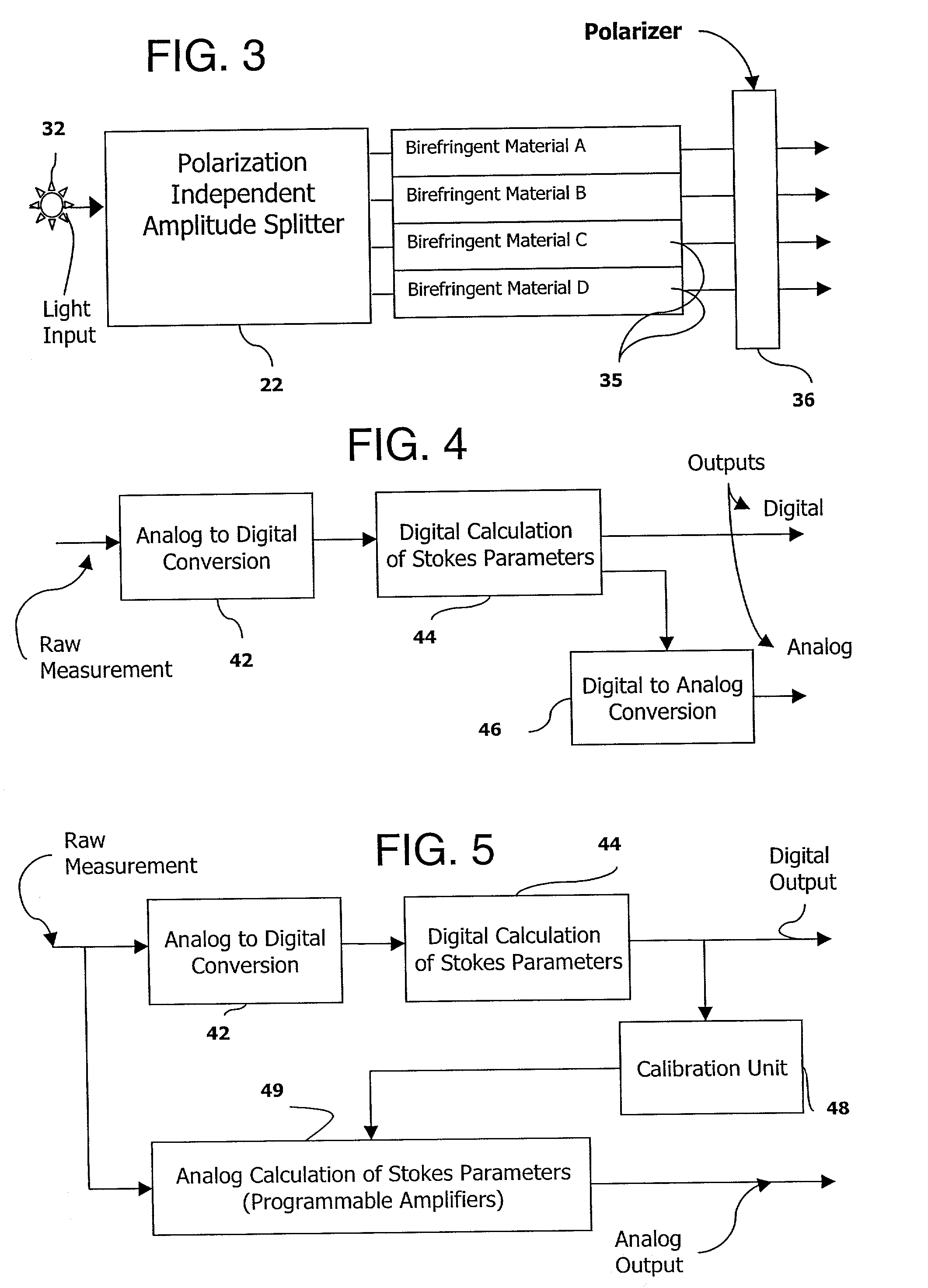
[0213] The examples provided used birefringent materials, including liquid crystal material, either tunable or otherwise arranged to produce four different instrument states as the minimum necessary to define Stokes values in a polarization analysis unit. Although liquid crystal material has many unique properties, which makes the material a desirable candidate for electro-optical control, the results are found not to be limited to or to depend on using this specific material.

[0214] Two Stacked Nematic Liquid Crystal (NLC) Cells

[0215] As shown in FIG. 15, the four points form a plane if the linear birefringence plate(s) used is (are) at a single orientation, while the only variable is the retardation(s), therefore, the enclosed volume is zero. Because of the zero enclosed volume, the determinant of the instrument matrix is also zero. Therefore, a simple means to produce four different instrument states is to use two nematic liquid crystal (NLC) cells, as s...


PUM


Abstract

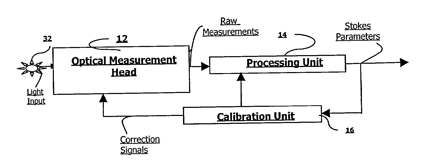
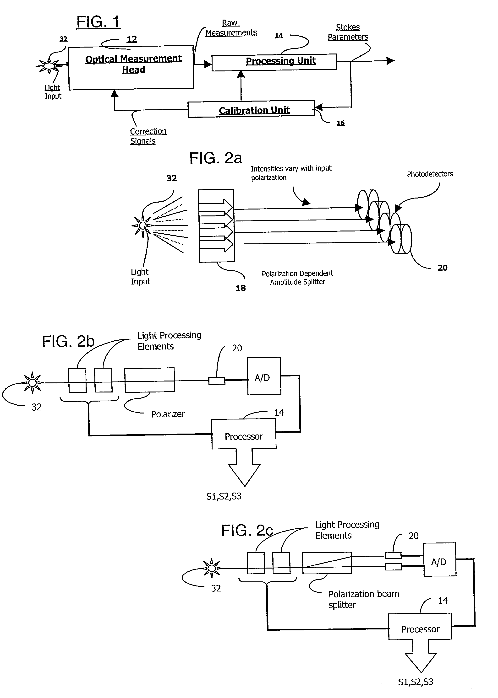
Measurements at multiple distinct polarization measurement states are taken to define the polarization state of an input, for example to calculate a Stokes vector. High accuracy and/or capability of frequent recalibration are needed, due to the sensitivity of measurement to retardation of the input signal. A multiple measurement technique takes a set of spatially and/or temporally distinct intensity measurements through distinct waveplates and polarizers. These can be optimized as to orientation and retardation using initial choices and also using tunable elements, especially controllable birefringence elements. A device matrix defines the response of the device at each of the measurement states. The matrix can be corrected using an iterative technique to revise the device matrix, potentially by automated recalibration. Two input signals (or preferably the same signal before and after a polarization transform) that are known to have a common polarization attribute or other attribute relationship are measured and the common attribute and/or attribute relationship is derived for each and compared. The device matrix is revised, for example by iterative correction or by random search of candidates to improve the accuracy of the device matrix. Optional tunable spectral and temporal discrimination provide additional functions.

Description

[0001] 1. Field of the Invention[0002] The invention relates to devices and methods for detecting, quantifying, indicating or otherwise responding to the polarization characteristics of an input electromagnetic signal, specifically a light input signal. The invention also relates to measurement of polarization aspects of light such as degree of polarization, extinction ratio measurements and one or two dimensional polarization mapping.[0003] Multiple measurements are taken in conjunction with filters and / or waveplates that process light or selectively pass portions of the input signal. These measurements discriminate among light signals having distinct polarization states or polarization components, by taking measurements at different relative phase relations and / or different orientations in space or time. According to an inventive aspect, the measurements are taken using certain tunable elements, arranged to provide the necessary diversity of measurement states to resolve polarizat...

Claims


Application Information

Patent Timeline
Patent Type & Authority Applications(United States)
IPC IPC(8): G01J3/447G01J4/00G01J4/04
CPCG01J3/447G01M11/331G01J4/04G01J4/00
Inventor PATEL, JAYANTILAL S.ZHUANG, ZHIZHONGYEAZELL, JOHN A.
Owner OPTELLIOS
Why Eureka
Try Eureka