Gas concentration sensor, hydrogen purification unit using this and fuel cell system

a technology of gas concentration sensor and hydrogen purification unit, which is applied in the direction of instruments, material heat development, specific gravity measurement, etc., can solve the problems of high cost, difficult to achieve, and poisoning of co in the reformed gas of the pt catalyst used in the electrodes

Inactive Publication Date: 2003-07-10
PANASONIC CORP
View PDF9 Cites 4 Cited by
  • Summary
  • Abstract
  • Description
  • Claims
  • Application Information

AI Technical Summary

Benefits of technology

0018] In this hydrogen purifier, it is effective that a temperature of the carbon monoxide purifying unit is controlled in correspondence with the concentration of the carbon monoxide.

Problems solved by technology

Moreover, in the case of fuel cells which operate at low temperatures of 100.degree. C. or lower such as solid polymer type fuel cells in vehicle-mounted or domestic uses, there is a possibility that a Pt catalyst used in the electrodes is poisoned with CO contained in the reformed gas.
However, application of a generally-implemented technique for detecting the CO concentration from absorption of ray of light of infrared wavelength due to CO, or technique for detecting the CO concentration from a change in resistance due to absorption of CO, is difficult at present because it does not function stably in the reformed gas or the cost thereof is high.
It has thus been difficult to always keep the oxygen to be supplied to the CO purifying catalyst in an optimum volume.
It has also been difficult at the time of start-up of the fuel cell system to determine whether the reformed gas can be supplied to the fuel cell or not even after sufficient removal of CO in the hydrogen purifier.
As thus been described, in the conventional technique, there is no step for detecting the CO concentration which is effective in the reformed gas, low-cost and reliable, making the CO purifying catalyst insufficiently exert the function thereof or necessitating a long-time standby operation of the fuel cell system before the start-up thereof at which the supply of the reformed gas to the fuel cell begins.

Method used


Image

  • Gas concentration sensor, hydrogen purification unit using this and fuel cell system
  • Gas concentration sensor, hydrogen purification unit using this and fuel cell system
  • Gas concentration sensor, hydrogen purification unit using this and fuel cell system

Examples


embodiment 1

[0024] In the following, Embodiment 1 of the present invention will be described with reference to the drawings:

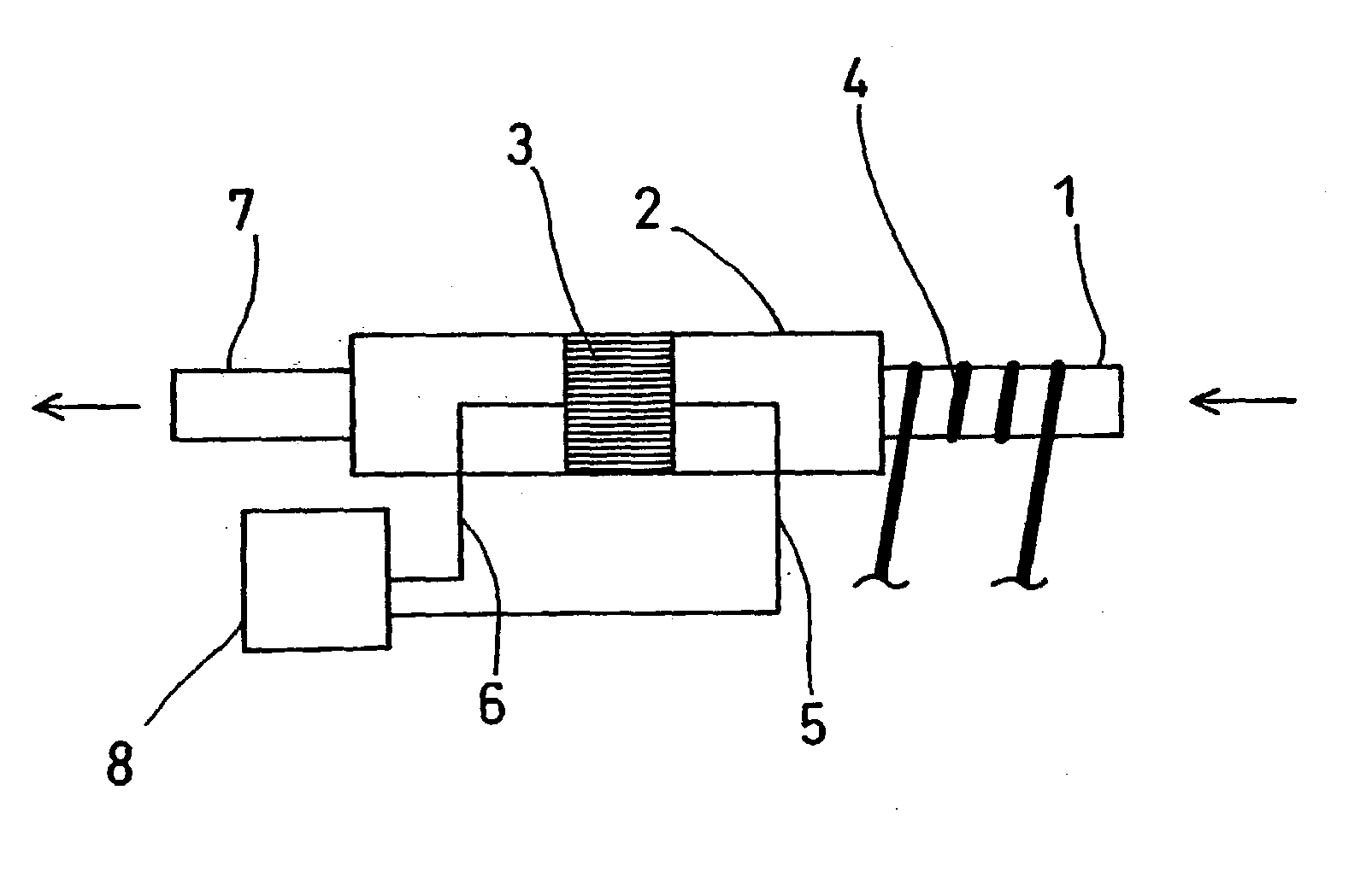
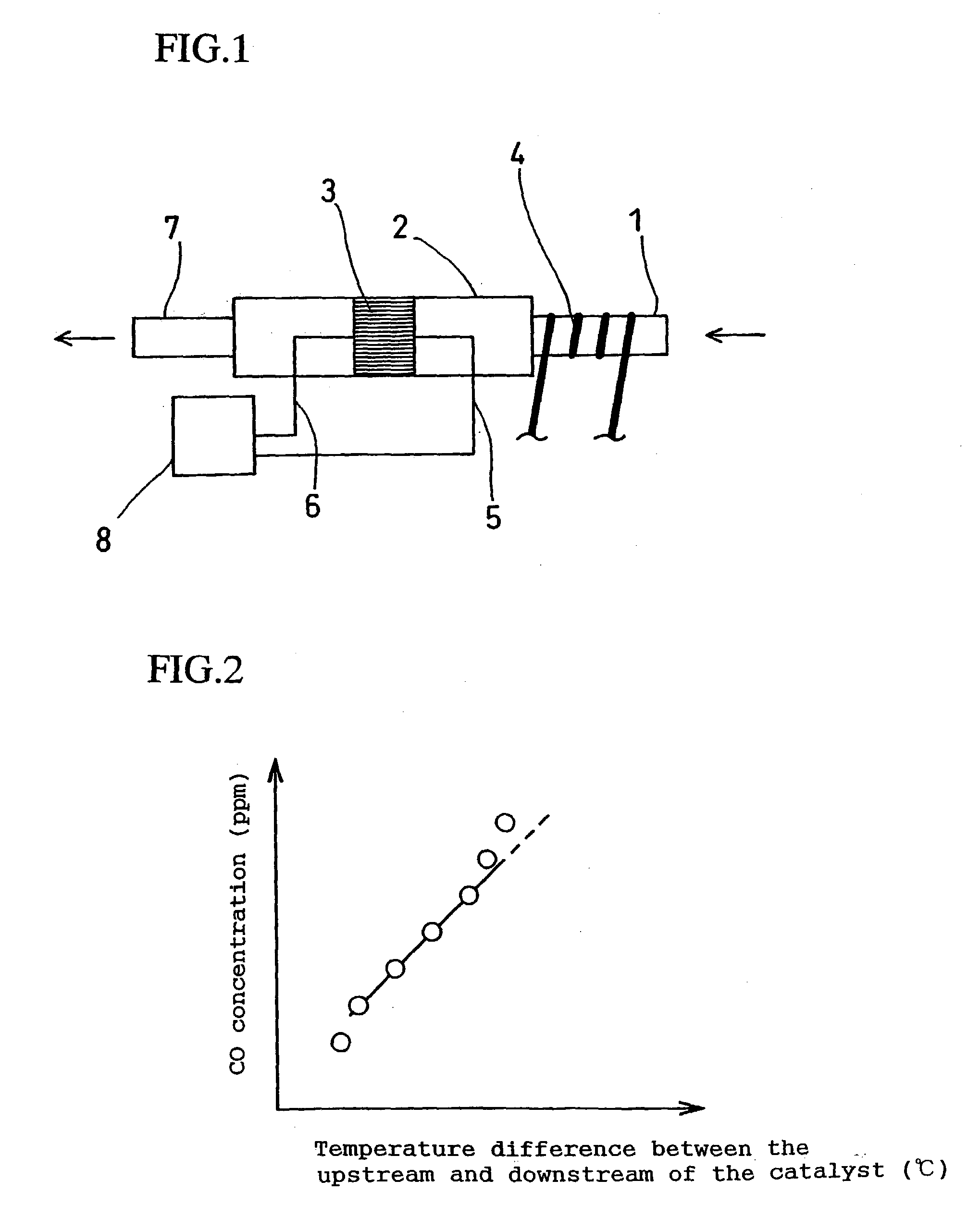
[0025] FIG. 1 is a schematic view showing a configuration of a gas concentration detector in accordance with Embodiment 1 of the present invention. In FIG. 1, a reformed gas supplied from a reformed gas inlet 1 (a gas containing at least hydrogen and carbon monoxide) is sent out to a reaction chamber 2, reacts in a catalyst layer 3 and is then discharged from out of a reformed gas outlet 7. A temperature upstream from the catalyst layer and a temperature downstream therefrom are measured on a first thermocouple 5 which is a first temperature detector and on a second thermocouple 6 which is a second temperature detector, respectively. Signals from these thermocouples are sent to a signal treatment device 8, to be output as a CO concentration.

[0026] Further, a heater 4 keeps the reaction chamber 2 at a constant temperature. Herein, a case of a reformed gas obtained when a na...

embodiment 2

[0047] Next, Embodiment 2 of the present invention will be described with reference to the drawings:

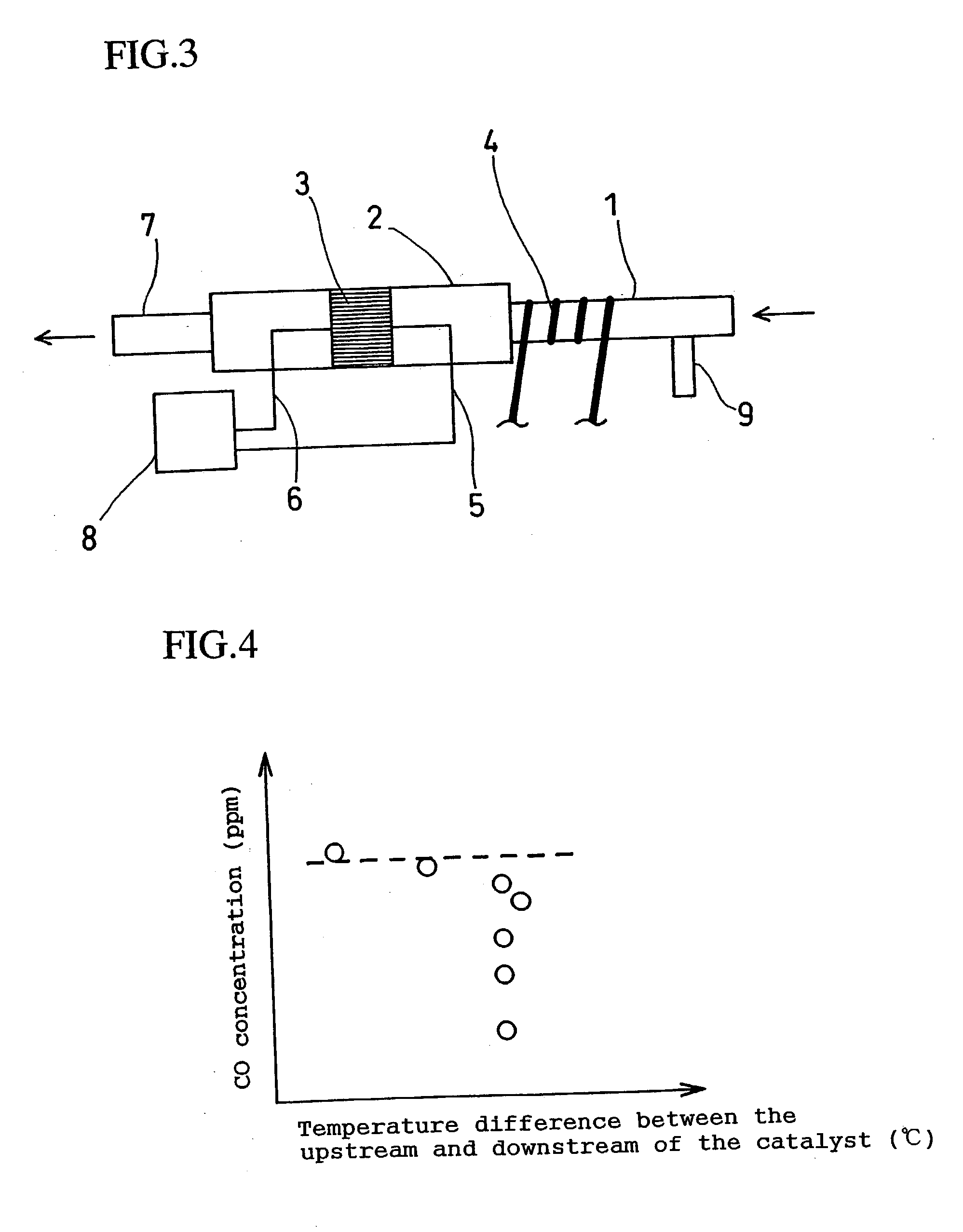
[0048] FIG. 3 is a schematic view showing a configuration of a gas concentration detector in accordance with Embodiment 2 of the present invention. In FIG. 3, a reformed gas supplied from a reformed gas inlet 1 is sent out to a reaction chamber 2, reacts in a catalyst layer 3 and is then discharged from out of a reformed gas outlet 7. A temperature upstream from the catalyst layer and a temperature downstream therefrom are measured on a first thermocouple 5 which is a first temperature detector and on a second thermocouple 6 which is a second temperature detector, respectively. Signals from these thermocouples are sent to a signal treatment device 8, to be output as a CO concentration.

[0049] Further, a heater 4 keeps the reaction chamber 2 at a constant temperature. A air supply unit 9 is arranged on the upstream side of the reaction chamber 2. In the present embodiment, a case of a r...

example 1

[0066] The reaction chamber 2 in the gas concentration detector shown in FIG. 1 was filled with a catalyst which is an almina pellet having a diameter of 1 mm and a length of 1 mm with 5% by weight of Ru carried thereon. A reformed gas composed of 20% by volume of carbon dioxide and the remaining t by volume of hydrogen was supplied from the reformed gas inlet at a flow rate of 0.1 liter per minute and the temperature of the first thermocouple was controlled to be 150.degree. C. in the heater 4. A reformed gas, mixed with CO such that the CO concentrations in the reformed gas were 5 ppm, 20 ppm, 100 ppm, 500 ppm, 900 ppm, 1200 ppm and 2000 ppm, was supplied and the temperatures of the first thermocouple and the second thermocouple were measured. The results of measurements of the CO concentrations (ppm) as well as the temperature differences between the upstream and the downstream (.degree. C.) were shown in Table 1.

1 TABLE 1 Temperature difference CO concentration between upstream / ...


PUM

PropertyMeasurementUnit
temperaturesaaaaaaaaaa

Abstract

In order to provide a step capable of reliably detecting a CO concentration in a reformed gas at low cost and a hydrogen purifier capable of fully exerting a function of a CO purifying catalyst, a gas concentration detector comprising a reaction chamber which has a catalyst layer and a gas temperature detector and capable of detecting the concentration of carbon monoxide in the gas by means of a signal of the temperature detector referring to a reformed gas passing along through the reaction chamber.

Description

TECHNICAL FIELD[0001] The present invention relates to a gas concentration detector and a hydrogen purifier. More specifically, it relates to an apparatus which is mainly composed of hydrogen to be used as a fuel for fuel cells and the like and detects the concentration of carbon oxide (CO) in a reformed gas containing CO, and the hydrogen purifier.BACKGROUND ART[0002] Hydrogen used for fuel cells and the like was conventionally generated by mixing steam with a hydrocarbon type fuel such as methane, propane, gasoline or kerosine, an alcohol type fuel such as methanol, or an ether type fuel such as dimethylether and bringing the mixed gas into contact with a heated reforming catalyst.[0003] In general, the hydrocarbon type fuel is reformed at temperatures of 500 to 800.degree. C. while the alcohol type fuel and ether type fuel are reformed at temperatures of 200 to 400.degree. C. CO generates in the reforming; as the reforming temperature is higher, the concentration of CO generating...

Claims


Application Information

Patent Timeline
Patent Type & Authority Applications(United States)
IPC IPC(8): G01N25/30G01N25/36G01N33/00H01M8/06
CPCG01N25/30G01N25/36G01N33/0026Y10T436/11H01M8/0662H01M8/0668Y10T436/23H01M8/0618Y02E60/50H01M8/04
Inventor TAGUCHI, KIYOSHITOMIZAWA, TAKESHIUKAI, KUNIHIRO
Owner PANASONIC CORP
Why Eureka
Try Eureka