Electrochemically driven monolithic microfluidic systems

a monolithic microfluidic and electrochemical technology, applied in the direction of polycrystalline material growth, mechanical equipment, separation processes, etc., can solve the problems of limited valve functional life and limited use of valves

Inactive Publication Date: 2003-08-14
THE RES FOUND OF STATE UNIV OF NEW YORK
View PDF2 Cites 19 Cited by
  • Summary
  • Abstract
  • Description
  • Claims
  • Application Information

AI Technical Summary

Problems solved by technology

As a further example, a bubble has been moved to and trapped at a flow restriction in a microchannel to itself serve as a valve for blocking flow, however such technology suffers from problems associated with removing the bubble from the channel flow path to allow flow to resume; see Ki, Y.
While electrochemical bubbles require low power in the microwatt range, and the bubble inflation rates are comparable to thermal bubbles, their use has been limited by slow bubble deflation rates, since the dissolution of gas into the fluid is kinetics-limited.
Moreover, in accordance with a present electrochemical embodiment, the functional life of the valve is limited only by the effective life of the electrodes.

Method used


Image

  • Electrochemically driven monolithic microfluidic systems
  • Electrochemically driven monolithic microfluidic systems
  • Electrochemically driven monolithic microfluidic systems

Examples


Embodiment Construction

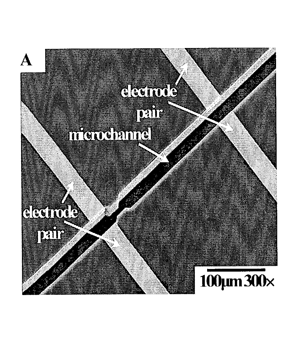
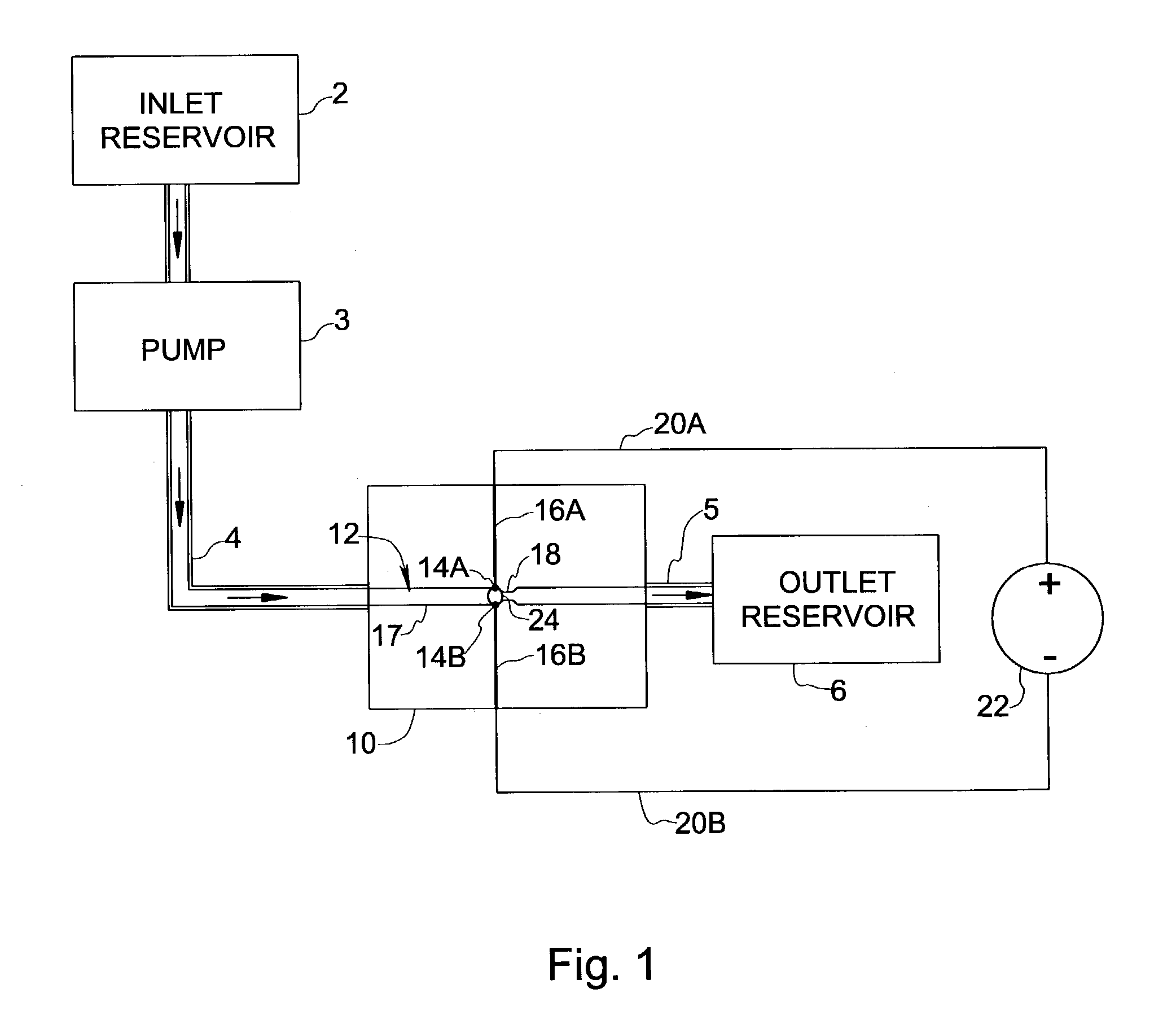
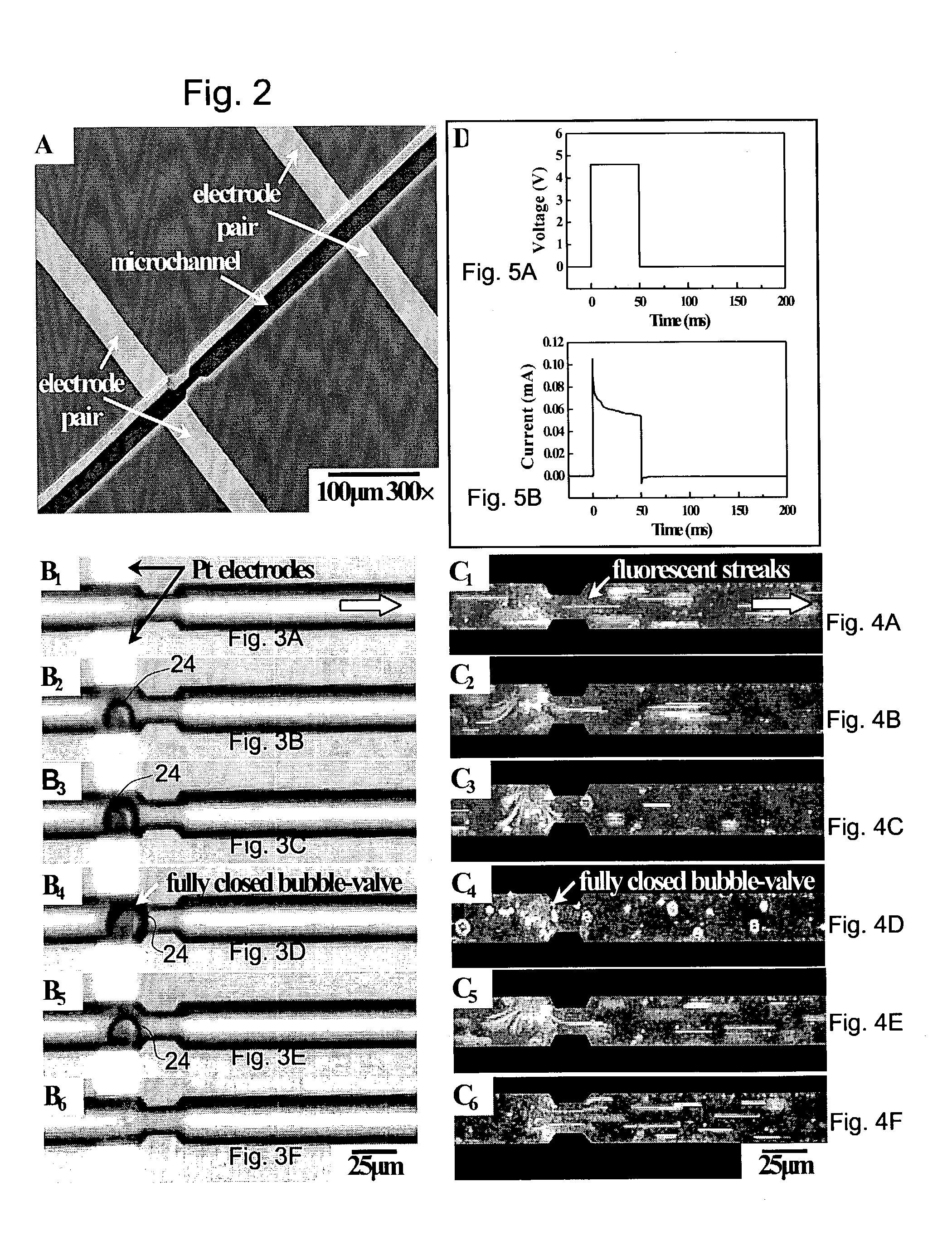
[0029] The microfluidic chips used to test the mechanical and chemical characteristics of bubble-valves consisted of a fluid channel connecting an inlet and an outlet reservoir, and anode / cathode electrode pairs perpendicular to the channel to generate bubble valves at different locations. FIG. 2 shows a scanning electron micrograph (SEM) of a portion of the channel (the inlet and outlet reservoirs are not shown) showing two sets of electrode pairs along the length of the channel. The microfluidic system was micromachined on a silicon wafer using standard microfabrication techniques. The channel was 25 .mu.m square in cross-section and 5.2 mm long. Near one pair of electrodes, a 15 .mu.m wide neck was introduced to create a backpressure, although from experiments it was subsequently found that surface forces alone were adequate and the neck was not needed to prevent the bubble from flowing downstream. Following photolithography, the channel was first etched to 25 .mu.m in depth usin...


PUM


Abstract

A microfluidic system and method, suitable for "lab-on-a-chip" applications, by which a bubble is inflated in fluid flowing through a microfluidic channel at a predetermined location along the channel and the bubble is maintained at that location to stop flow through the channel in the manner of a valve. The microfluidic channel is formed on a semiconductor chip and a pair of electrodes is formed one on each side of the channel, whereby a bubble is electrochemically inflated between the electrodes and held in fixed position by the channel wall when a voltage is applied across the fluid incident to connecting the electrodes to a voltage source. When the voltage is removed, deflation of the bubble valve rapidly occurs to restore flow. The present invention provides flow control in a microfluidic system regardless of channel cross-sectional geometry and with no moving parts and low power consumption. Moreover, the present invention may be practiced using existing fabrication techniques.

Description

CROSS-REFERENCES TO RELATED APPLICATIONS[0001] This application claims the benefit of U.S. Provisional Application No. 60 / 333834 filed Nov. 28, 2001.[0003] The present invention relates generally to the field of microfluidic systems, and more particularly to a method and apparatus for regulating fluid flow through a microfluidic channel.DESCRIPTION OF RELATED ART[0004] Micro-electromechanical systems (MEMS) continue to spawn new technological applications and serve as catalysts for key scientific discoveries. Intense efforts are currently underway to develop multi-functional microfluidic chips, a technology commonly referred to as "lab-on-a-chip". Applications include, among others, combinatorial and analytical chemistry, drug discovery, microbiology, biotechnology, and drug delivery. To regulate fluid flow through labyrinthine microfluidic channels using pumps and valves, various actuation mechanisms, based on piezoelectricity, electrostatics, thermo-pneumatic, and electromagnetism...

Claims


Application Information

Patent Timeline
Patent Type & Authority Applications(United States)
IPC IPC(8): F15C5/00F16K99/00
CPCF15C5/00F16K99/0001F16K99/0019F16K2099/0084F16K2099/0074F16K2099/008F16K99/0042
Inventor HUA, ZONGLU SUSANCHOPRA, HARSH DEEPSACHS, FREDERICK
Owner THE RES FOUND OF STATE UNIV OF NEW YORK
Why Eureka
Try Eureka