Methods of manufacturing electron-emitting device, electron source, and image display apparatus

a technology of image display apparatus and electron source, which is applied in the manufacture of electrode systems, tube/lamp factory adjustment, and screen tubes, etc., can solve the problems of complex management of respective steps and the manufacture of image-forming apparatuses that use such conventional methods

Inactive Publication Date: 2003-08-28
CANON KK
View PDF31 Cites 19 Cited by
  • Summary
  • Abstract
  • Description
  • Claims
  • Application Information

AI Technical Summary

Benefits of technology

[0020] The present invention has been made in view of the above, and therefore has an object to provide a method of manufacturing an electron-emitting device which particularly attains simplification of manufacturing steps of the electron-emitting device and improvement of electron-emitting characteristics, a method of manufacturing an electron source, and a method of manufacturing an image-forming apparatus.
[0021] The present invention has been made as a result of extensive studies for solving the above-mentioned problems and has the structures described below.

Problems solved by technology

However, manufacturing of an image-forming apparatus that uses such a conventional electron-emitting device has the following problems.
That is, the manufacturing includes many additional steps such as repeated energization steps in the "energization forming step" and the "activation step" and a step of forming a preferable atmosphere in each step, and thus, management of respective steps has been complicated.

Method used


Image

  • Methods of manufacturing electron-emitting device, electron source, and image display apparatus
  • Methods of manufacturing electron-emitting device, electron source, and image display apparatus
  • Methods of manufacturing electron-emitting device, electron source, and image display apparatus

Examples


embodiment

[0213] The present invention will be hereinafter described more in detail with reference to embodiments.

first embodiment

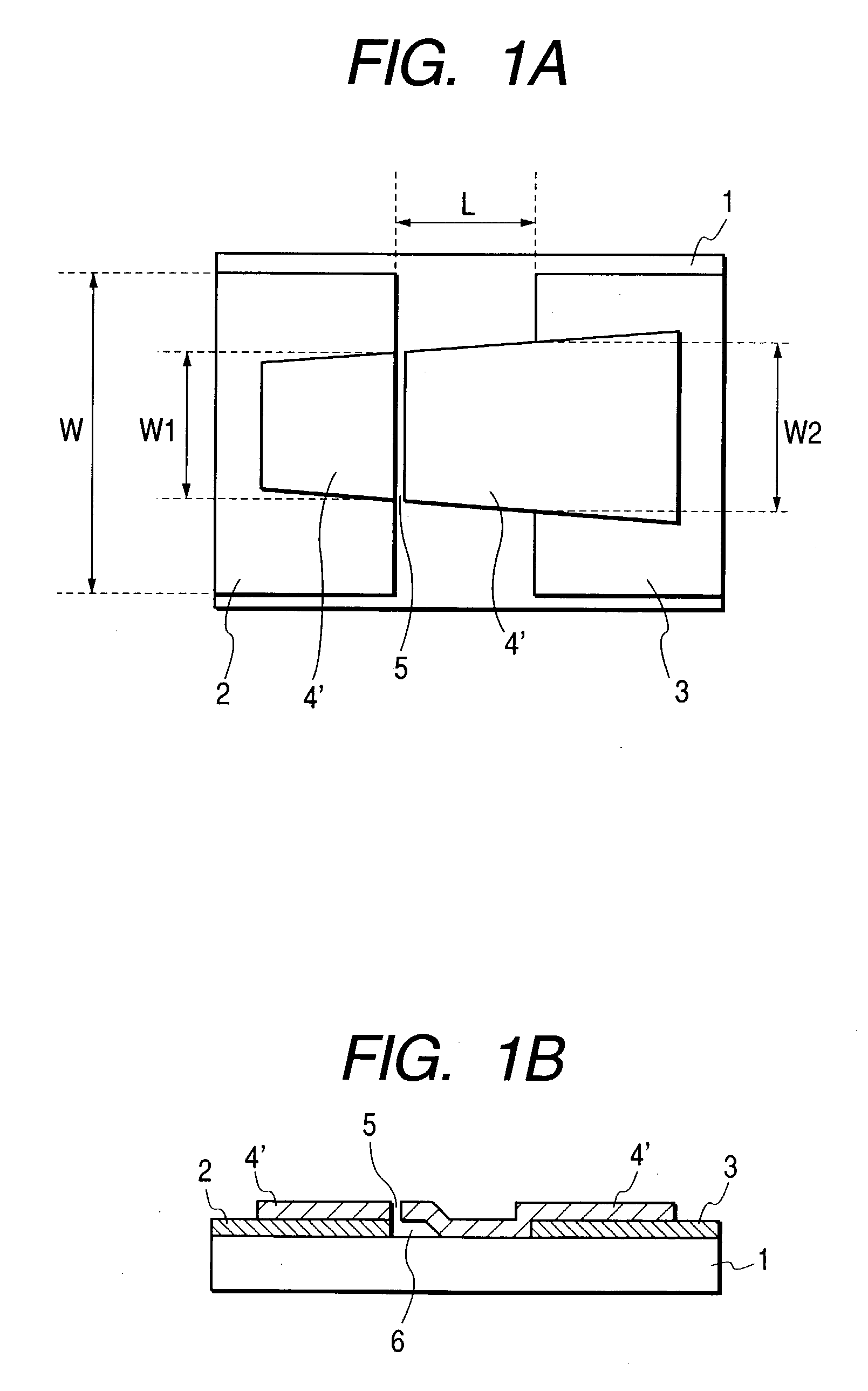
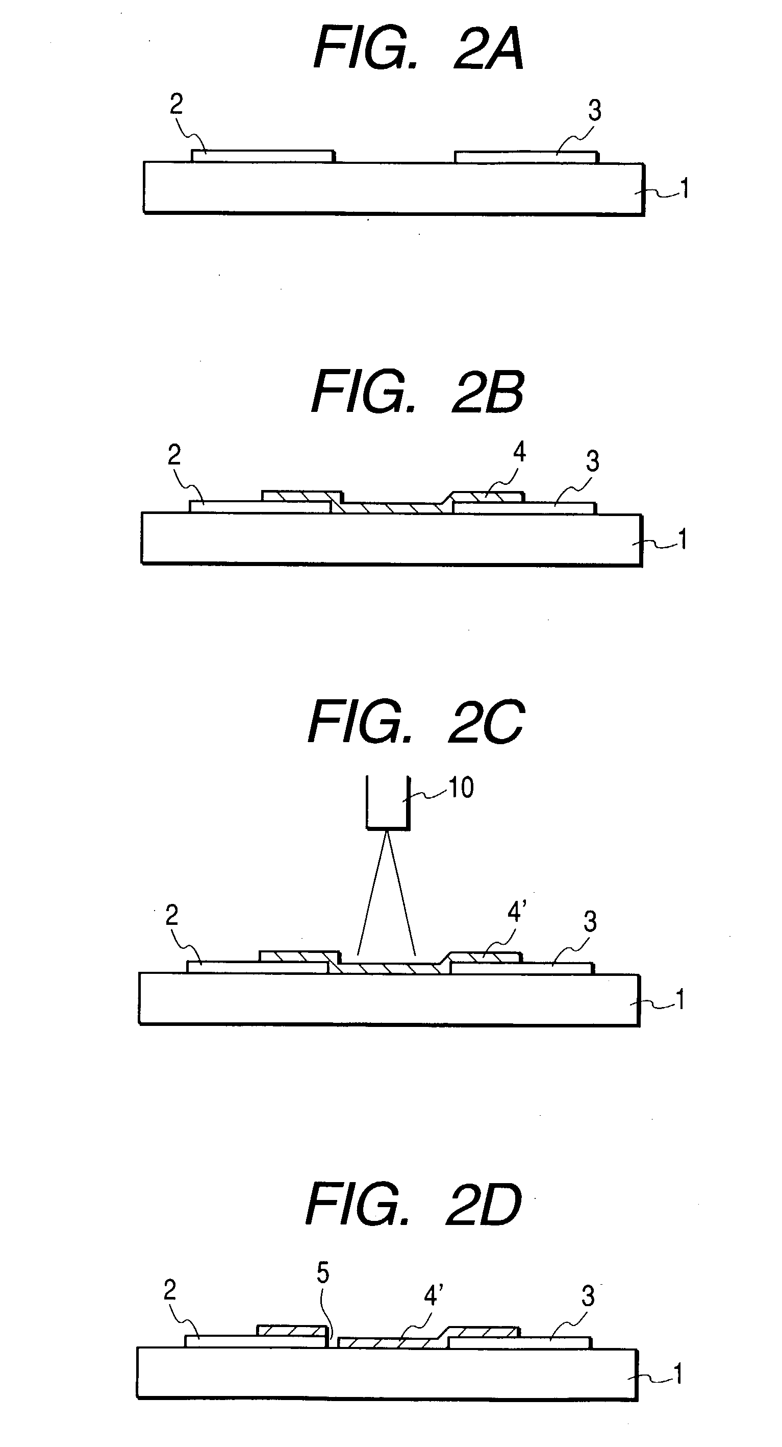
[0214] In this embodiment, the electron-emitting device manufactured by the manufacturing method shown in FIGS. 2A to 2D was used. Details of the manufacturing process will be hereinafter described.

[0215] Step 1

[0216] A Pt film with a thickness of 100 nm was deposited on the glass substrate 1 by the sputtering method, and electrodes 2 and 3 consisting of the Pt film were formed with the photolithography technique (FIG. 2A). Note that a distance between the electrodes 2 and 3 was set to 10 .mu.m. "PD200" manufactured by Asahi Glass Co., Ltd. was used as the substrate 1. Physical property values of this glass are as follows: specific heat: C.sub.sub=653 J / kg.multidot.K, specific gravity: .rho..sub.sub=2730 kg / m.sup.3, and heat conductivity: .lambda..sub.Sub=0.09 W / m.multidot.K. In addition, when an absorption coefficient of a wavelength around 800 nm of this glass was measured, it was approximately 5%. Further, a not-shown wiring for supplying a current is connected to the electrodes ...

second embodiment

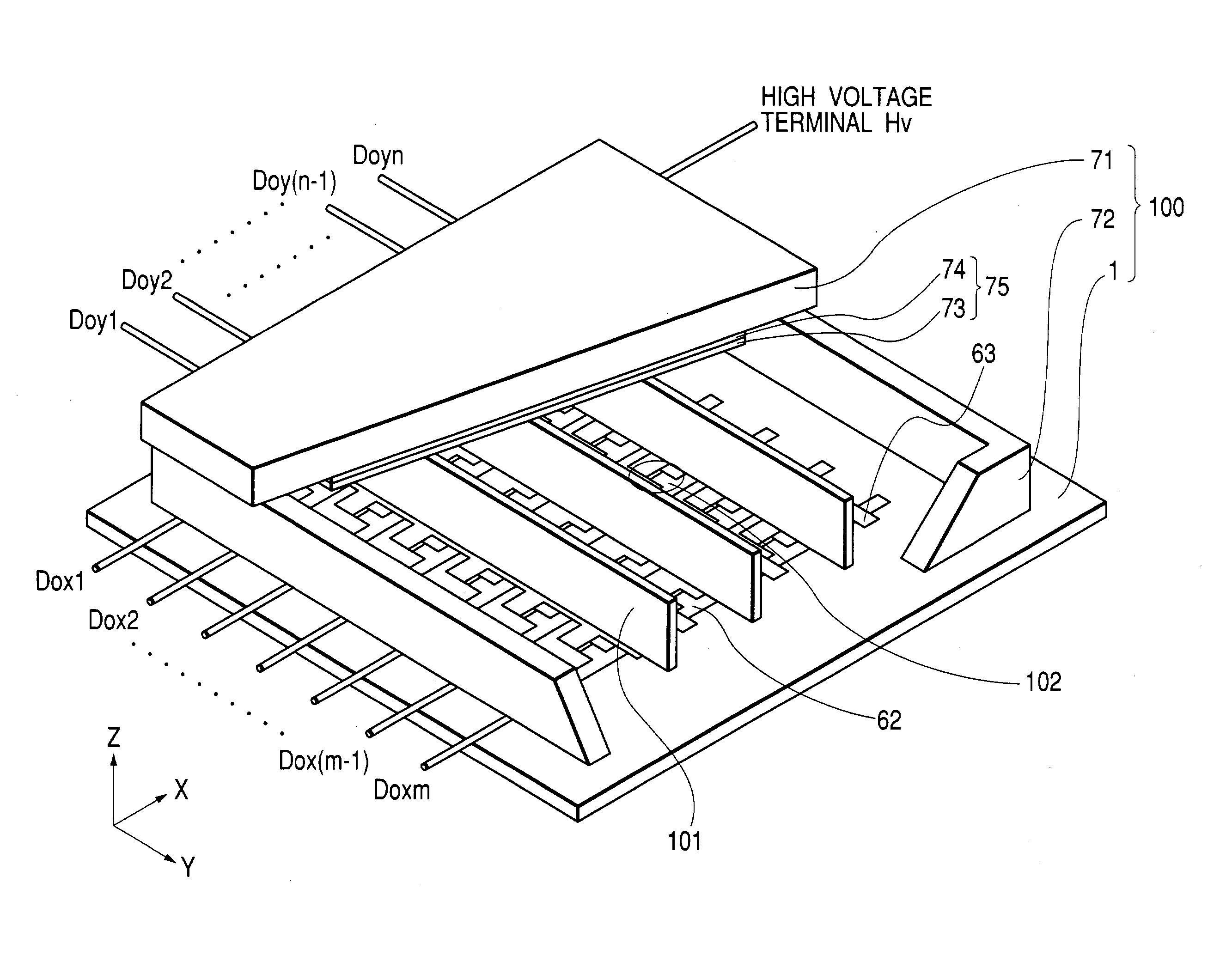
[0236] In this embodiment, an image-forming apparatus 100 schematically shown in FIG. 16 was manufactured. Reference numeral 102 denotes an electron-emitting device of the present invention. A method of manufacturing the image-forming apparatus of this embodiment will be described with reference to FIGS. 6 to 12, FIG. 16, FIGS. 17A and 17B.

[0237] FIG. 12 schematically shows a part of an electron source, which is constituted by a rear plate 1, a plurality of electron-emitting devices of the present invention formed on the rear plate 1, and wiring for applying a signal to each electron-emitting device, in an enlarged manner. Reference numeral 1 denotes a rear plate; 2 and 3, electrodes; 5', a gap; 4', a carbon film; 62, X-directional wiring; 63, Y-directional wiring; and 64, an interlayer insulating layer.

[0238] PD200 of Asahi Glass Co., Ltd. was used as the rear plate 1. Each property value is as follows:

[0239] Specific heat: C.sub.sub=653 J / kg.multidot.K

[0240] Specific gravity: .rho...


PUM


Abstract

In a process of reducing a resistivity of a polymer film for carbonization in a surface conduction electron-emitting device, by irradiating an energy beam onto the polymer film, when an energy intensity of the beam given in a unit area in a unit time is assumed to be W W / m2, W satisfies a formula W>=2xTx(rhosub.Csub.lambdsub / T)1 / 2, where T is defined as a temperature ° C. at which the polymer film is heated for one hour in a vacuum degree of 1x10⁻⁴ Pa to reduce a resistivity of the polymer film to 0.1 OMEGA.cm, Csub is a specific heat J / kg.K of the substrate, rhosub is a specific gravity kg / m3 of the substrate, lambdsub is a heat conductivity W / m.K of the substrate, and T is an irradiation time in the range of 10-9 sec to 10 sec.

Description

[0001] 1. Field of the Invention[0002] The present invention relates to a method of manufacturing an electron-emitting device, a method of manufacturing an electron source by processing units into a large number of electron-emitting devices, and a method of manufacturing an image-forming apparatus, such as an image display apparatus, which is structured by using the electron source.[0003] 2. Related Background Art[0004] Up to now, a surface conduction electron-emitting device has been known as an electron-emitting device.[0005] A structure, a manufacturing method, and the like of the surface conduction electron-emitting device are disclosed, for example, in Japanese Patent Laid-open Gazette No. 8-321254.[0006] A structure of a typical surface conduction electron-emitting device disclosed in the above-mentioned publication or the like is schematically shown in FIGS. 13A and 13B, which are respectively a plan view and a sectional view of the surface conduction electron-emitting device...

Claims


Application Information

Patent Timeline
Patent Type & Authority Applications(United States)
IPC IPC(8): H01J9/02H01J1/316H01J9/00H01J9/04H01J9/24H01J31/12
CPCH01J31/127H01J9/027
Inventor MIZUNO, HIRONOBUIWAKI, TAKASHITAKEDA, TOSHIHIKOSUZUKI, NORITAKEMIYAZAKI, KAZUYANUKANOBU, KOKI
Owner CANON KK
Why Eureka
Try Eureka