[0030] The
depth of penetration of susceptor must allow for applied UV energy to penetrate the susceptor for volumetric interaction a) with the susceptor to produce
fluorescent radiation and / or b) directly between the applied UV energy and gaseous / particulate species. Consequently, if UV and
microwave energies are applied to the same susceptor, other interactions may occur between the applied energies, material of construction of the susceptor, field concentrators and the gaseous species (or particulate). The UV energy that is applied to the cavity can interact as previously mentioned, however the
microwave energy a) may produce
thermoluminescence in the phosphorescent materials b) may produce heat in the susceptor by the applied
microwave energy and / or c) may enhance the phosphorescent
radiation produce primarily by the applied UV energy. Of other consequence, if the applied energy to the same susceptor is only microwave energy then other interactions may occur. The microwave energy either a) may be completely absorbed for
thermal treatment of the gases, b) may be partially absorbed and interact with the gaseous species for interaction, c) may be used to heat the susceptor and produce thermophosphorescence of UV
radiation, which interacts with the gaseous species, or d) a combination of the mentioned interactions in a, b, and c.
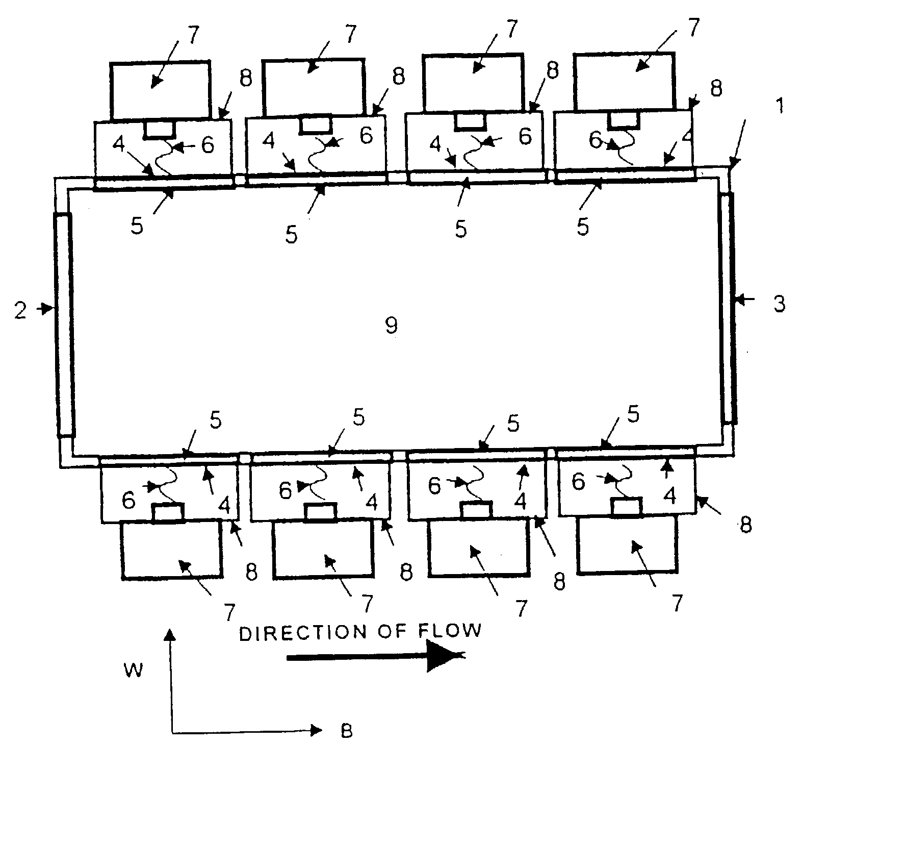
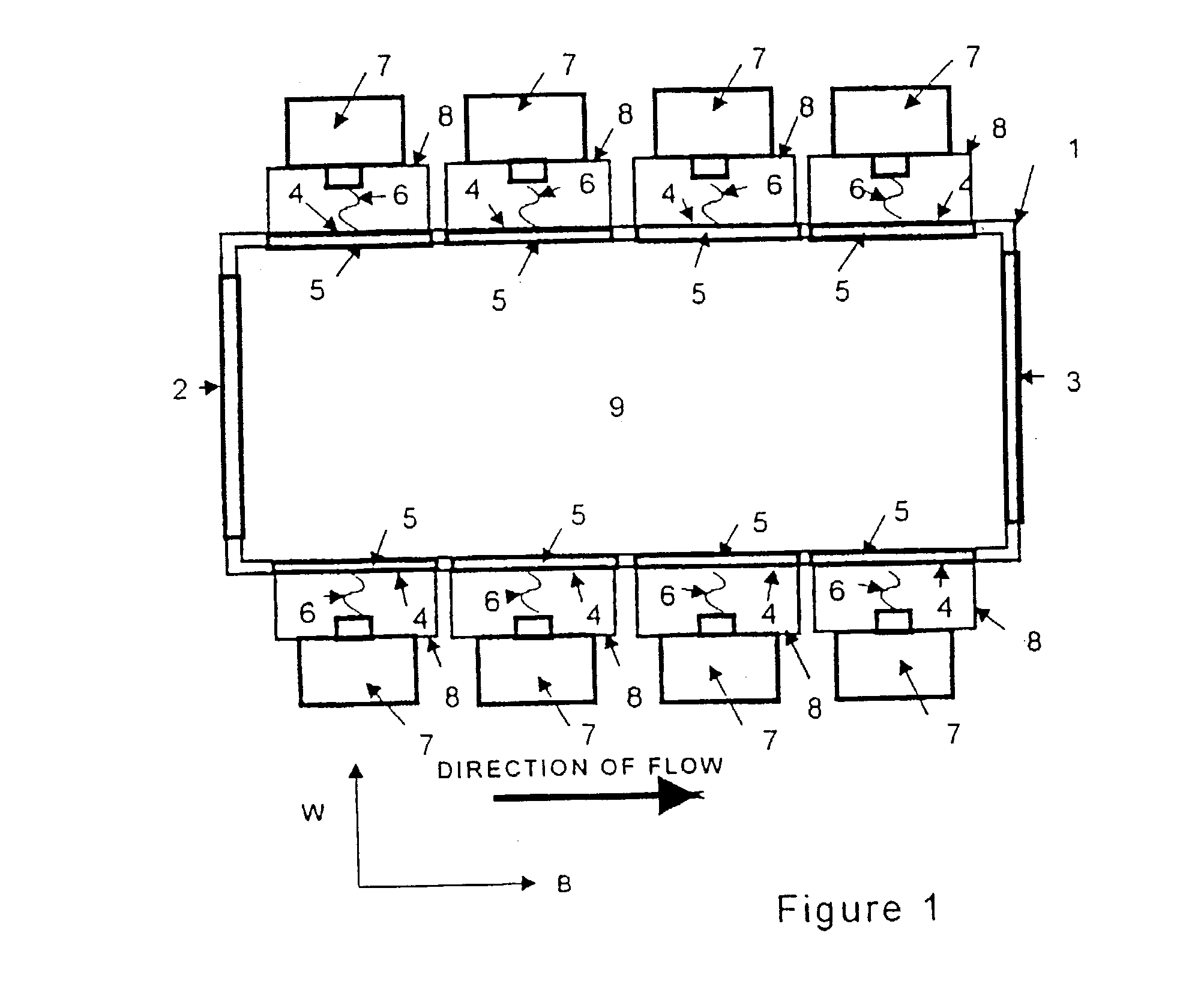
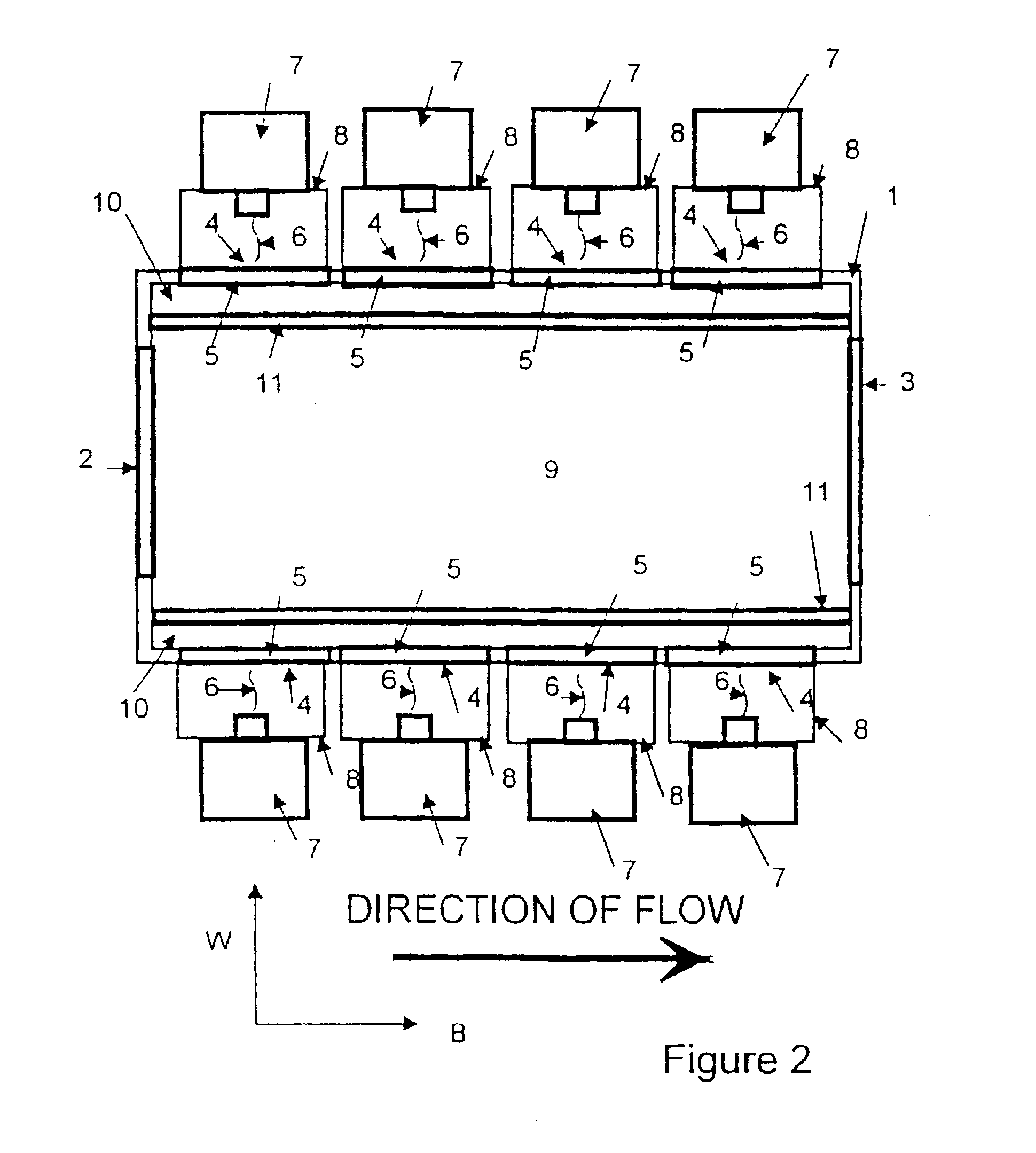
[0036] In this broadest sense of the invention, the cavity's geometrical cross-sectional area perpendicular to the flow of the air
stream and the susceptor's width of interaction is designed to provide in this device a more homogenous distribution of energy with a given amount of applied power. With the more
homogeneous distribution of energy, the invention allows for one to design a method for specific treatment of gaseous and particulate species, compared to designing treatment methods with devices that have geometries that concentrate electromagnetic energy such as a cylinder. With this invention, the
depth of penetration of the susceptor by the applied electromagnetic energy or energy allows one to
design methods of destroying
pollution and reacting gases / particulate species. When the depth of the penetration of the susceptor is one third (1 / 3) the width of the susceptor's total width or greater, the method of treatment of gases / particulate can be either 1) primarily thermal, 2) a combination of thermal, fluorescent, thermoluminescent, and interaction between the applied energy or energies and the gas or particulate in the air
stream, or 3) when scattering of the applied energy is used to concentrate the applied energy without producing substantial heating of susceptor, such as with a low loss, low dielectric constant susceptor constructed with metallic spheres and fused silica, the device can primary treat by interaction between the applied energy or energies and the gas or particulate in the air stream.
[0038] Another aspect of this invention is a
heat transfer process to increase the efficiency of such devices, which treat gases for
chemical reaction, or destruction of pollutants. Commercially available magnetrons are generally between 65-70% efficient. Therefore 30-35% of the energy that is initially put into the
system is lost. An aspect of this invention is a
heat transfer process for using that energy.
[0039] In this
heat transfer process, heat is transferred between
heat energy that is produced by the tube or tubes which supplies the applied electromagnetic energy and an input
chemical species flow that can contain gases and particulate species. The process uses the heat from the tubes or tubes to preheat the input
chemical species flow, or part of the input
chemical species flow, prior to it entering the device. This
heat transfer process for preheating the input chemical species flow will decrease the cost of operating such a device. The heat from the tube, or tubes, can be exchanged with the input chemical species flow by such cooling fins that are found on commercial magnetrons, heat pipes, thermoelectric devices, or cooling systems that circulate a fluid around the tube and release the heat at radiator. After the input chemical species flow is preheated with heat from the tube, the input chemical species flow can be further heated by heat transfer either a) from the cavity walls, b) from a conventional
heat exchanger (a
recuperator) that is located after the exit end of the device, or c) from both the cavity walls and a conventional
recuperator.
[0049] A high degree of
interconnectivity can be beneficial in some instances. Clusters of primarily reflective unit susceptors can be distributed about the macroscopic artificial susceptor to promote scattering. Primarily reflective unit susceptors can be aggregated to form shapes and boundaries that reflect one or more wavelengths of the applied energy or energies. The
volume fraction and
interconnectivity of the reflective unit susceptors surrounding primarily absorbing or primarily transparent unit susceptors can be used to design specific macroscopic artificial dielectric structures a) for resonant cavities with that are based upon the
wavelength of the applied energy in the susceptor, b) for scattering energy for interaction with gas or particulate species, c) that concentrate energy at field concentrators which are located on other unit susceptors, d) that concentrate energy within the susceptor for increased reactivity between the gas stream and the
fluorescent radiation, e) that have the primarily reflective unit susceptors arranged in such a manner to produce a large spiral,
helical or other shape with the macroscopic susceptor, f) that act as shielding to prevent the applied electromagnetic from entering material inside the cavity for
thermal insulation, g) that prevent leakage outside the cavity by the applied energy, h) that reflect applied energy to other regions of the artificial dielectric to provide either higher temperatures or increased energy for reaction or destruction of gaseous / particulate species and i) possibly, that regulate the temperature of the gas-stream.

