Process for the manufacture of membrane-electrode-assemblies using catalyst-coated membranes

a technology of catalyst-coated membranes and assembly processes, which is applied in the direction of fuel cells, coatings, cells, etc., can solve the problems of low catalyst utilisation, the need to separate assembly of catalyst-coated membranes, and the damage or perforation of membranes, so as to simplify the assembly of products into pemfc and dmfc stacks and improve the performance of five-layer meas

Active Publication Date: 2003-12-04
UMICORE AG & CO KG
View PDF6 Cites 40 Cited by
  • Summary
  • Abstract
  • Description
  • Claims
  • Application Information

AI Technical Summary

Benefits of technology

[0014] The five-layer MEA is assembled together by means of a lamination process involving an adhesive component. The anode gas diffusion layer, the catalyst-coated membrane and the cathode gas diffusion layer are combined together by a low temperature / low pressure lamination process. Handling of the MEAs and assembly of the products into PEMFC and DMFC stacks is simplified. Less damage and perforation of the catalyst-coated membrane occurs and thus the performance of the five-layer MEAs is significantly improved.

Problems solved by technology
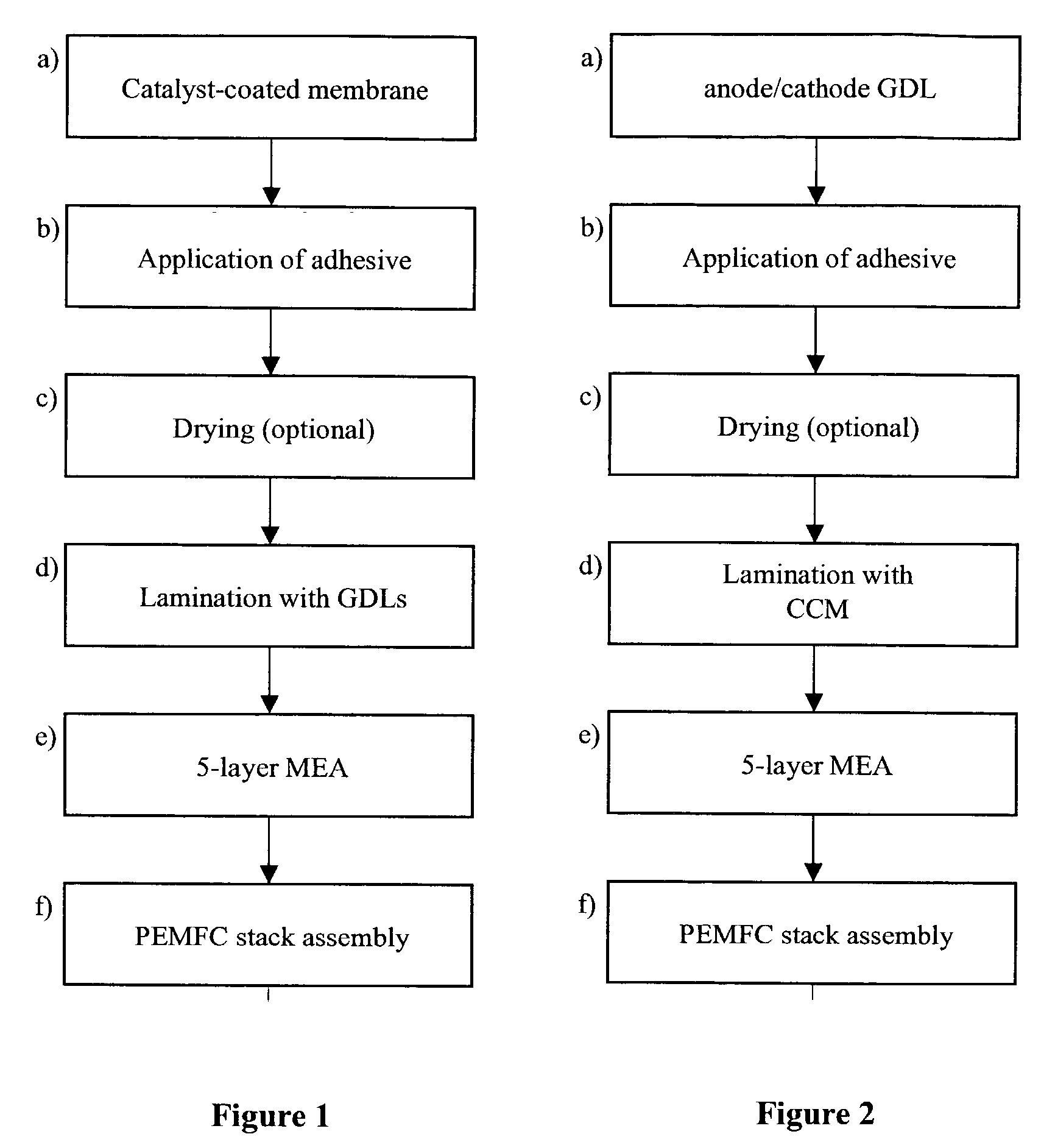
The drawback is that the catalyst-coated membrane (CCM) needs to be assembled separately with two GDLs when making a fuel cell stack.
This may lead to membrane damage or perforation, particularly if thin ionomer membranes (with less than 40 .mu.m thickness) are used.
Furthermore, the catalyst layer on the GDL substrate may be damaged and / or densified, which results in a low catalyst utilisation and a low performance.
Furthermore, no details are given in respect to performance and quality of the MEAs produced according to the claimed processes.
Thus, the stack assembly process comprises various alignment steps with different components and is very time-consuming and expensive.

Method used


Image

  • Process for the manufacture of membrane-electrode-assemblies using catalyst-coated membranes
  • Process for the manufacture of membrane-electrode-assemblies using catalyst-coated membranes

Examples


example 1

[0041] A catalyst-coated membrane (CCM Type R221, reformate operation / full humidification, active area 50 cm.sup.2; OMG AG & Co. KG, Hanau) was used as the CCM component. The anode electrode side contained a PtRu / C electrocatalyst and had a total precious metal loading of 0.45 mg (0.3 mg Pt / cm.sup.2 and 0.15 mg Ru / cm.sup.2), the cathode side contained a Pt / C electrocatalyst with a Pt loading of 0.4 mg Pt / cm.sup.2.

[0042] The anode GDL, hereinafter referred to as GDL(A), was prepared as follows: A sheet of carbon fiber paper (thickness 350 .mu.m, porosity 85%; supplied by SGL Carbon Group, type SIGRACET.RTM.) was wet proofed with a water based PTFE solution (type Hostaflon TF 5032, Dyneon.RTM.g, Gendorf) to a PTFE content of 16 wt. % and a microlayer, consisting of carbon black and PTFE was applied to one side of the carbon paper by screen printing. The cathode GDL, hereinafter referred to as GDL(C), was prepared accordingly, however, the PTFE content was reduced to 9 wt. % in the wet...

example 2

[0045] A catalyst-coated membrane (CCM Type R221, active area 50 cm.sup.2; OMG AG & Co. KG) was used as the CCM component. GDL(A) and GDL(C) were prepared as described in example 1. A catalyst-containing paste was formulated according to the following composition:

1 15.0 g Electrocatalyst Elyst .TM. A 40 (OMG AG, Hanau) 50.0 g Nafion .RTM. SE 10072 (10 wt. % in water, DuPont) 35.0 g Dipropylene glycol 100.0 g

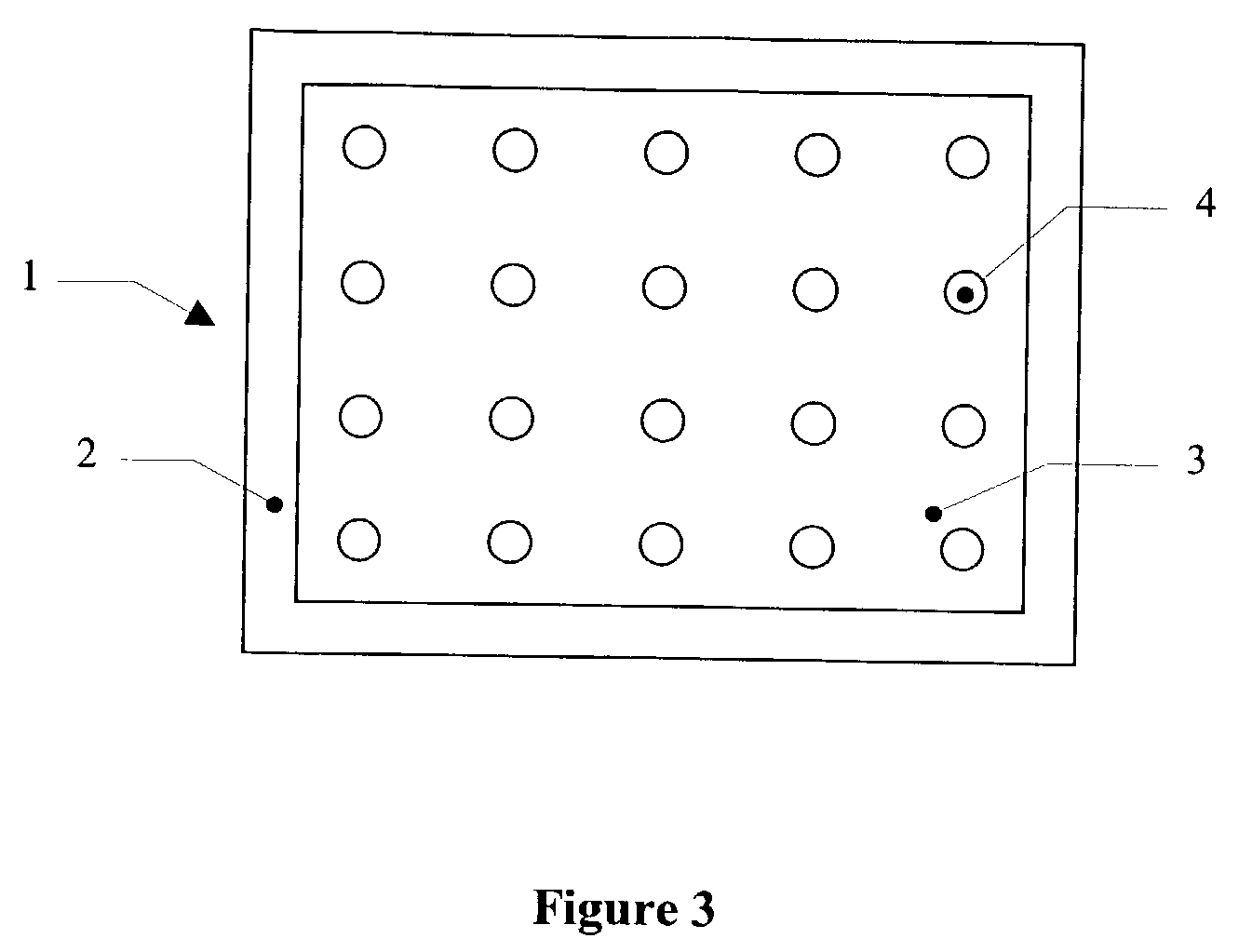
[0046] The catalyst-containing paste was applied in a fine dot pattern onto the anode side of the active area of the CCM. The diameter of the dots was 1 mm, an automatic dispenser unit with a needle of 0.5 mm diameter was used. In a second step, the same amount of catalyst-containing paste was applied onto the microlayer-coated side of the cathode backing GDL(C). After drying at 80.degree. C. for 2 minutes, the CCM was sandwiched between anode GDL(A) and cathode GDL(C). This assembly was subsequently hot pressed at 120.degree. C. at a pressure of 8 bar. A flexible five-layer MEA ...

example 3

[0047] A catalyst-coated membrane (CCM Type R221, active area 50 cm.sup.2; OMG AG & Co. KG) was used. Anode and cathode GDLs were prepared as described in example 1. A carbon black-containing adhesive paste was prepared with the following composition:

2 20.0 g Carbon Black Shawinigan (Chevron) 60.0 g Nafion .RTM. SE 10072 (10 wt. % in water, DuPont) 20.0 g Dipropylene glycol 100.0 g

[0048] The carbon black-containing adhesive paste was selectively screen printed onto the microlayer-coated side of the anode and the cathode GDLs. The drying step was omitted. The further processing was as described in example 2. A five-layer MEA with very good electrical performance was obtained (Table 1)

[0049] Electrochemical Testing

[0050] The five-layer MEAs were tested in a PEMFC single cell with an active area of 50 cm.sup.2 running on reformate / air conditions with simulated natural gas reformate (composition 40 vol.-% hydrogen, 40 vol.-% nitrogen, 20 vol.-% carbon dioxide, 40 ppm carbon monoxide and...


PUM

PropertyMeasurementUnit
temperatureaaaaaaaaaa
pressureaaaaaaaaaa

Abstract

The present invention relates to the field of electrochemical cells and fuel cells, more specifically to polymer-electrolyte-membrane (PEM) fuel cells and describes a process for the manufacture of membrane-electrode-assemblies (MEAs) containing five layers. The five-layer MEA is assembled together by means of a lamination process involving an adhesive component. The anode gas diffusion layer, the catalyst-coated membrane and the cathode gas diffusion layer are combined together by a low temperature / low pressure lamination process. Handling of the MEAs and assembly of the products into PEMFC and DMFC stacks is simplified. Less damage and perforation of the catalyst-coated membrane occurs and thus the performance of the five-layer MEAs is significantly improved.

Description

[0001] The present invention relates to the field of electrochemical cells and fuel cells, more specifically to polymer-electrolyte-membrane (PEM) fuel cells and describes a process for the manufacture of membrane-electrode-assemblies (MEAs).[0002] Fuel cells convert a fuel and an oxidising agent into electricity, heat and water at two spatially separated electrodes. Hydrogen or a hydrogen-rich gas can be used as the fuel and oxygen or air as the oxidising agent. The energy conversion process in the fuel cell is distinguished by particularly high efficiency. For this reason, fuel cells are gaining increasing importance as an alternative to conventional combustion engines. Furthermore, they are used in stationary combined-heat-and-power units (CHP), as well as in portable applications.[0003] The polymer electrolyte membrane fuel cell (PEMFC) and the direct methanol fuel cell (DMFC, a variation of the PEMFC, powered directly by methanol instead of hydrogen) are suitable for use as ene...

Claims


Application Information

Patent Timeline
Patent Type & Authority Applications(United States)
IPC IPC(8): B01D67/00B01D71/00C25B9/23H01M8/02H01M4/88H01M4/92H01M4/94H01M8/00H01M8/10H01M8/24
CPCH01M4/881H01M4/921Y02E60/523H01M8/0284H01M8/1004H01M4/926Y02E60/50Y02P70/50H01M4/88
Inventor KOHLER, JOACHIMFEHL, KNUTKRAMER, ANITAWITTPAHL, SANDRASCHAACK, KLAUS
Owner UMICORE AG & CO KG
Why Eureka
Try Eureka