Photoelectron linear accelerator for producing a low emittance polarized electron beam

a polarized electron and linear accelerator technology, applied in the direction of irradiation devices, nuclear engineering, therapy, etc., can solve the problems of large energy reduction, large energy reduction, and the effect of the space charge field still remains

Inactive Publication Date: 2004-04-01
DULY RES
View PDF4 Cites 9 Cited by
  • Summary
  • Abstract
  • Description
  • Claims
  • Application Information

AI Technical Summary

Problems solved by technology

The problem for a dc gun is not the gradient on the cathode, which can be fairly high and potentially even as high as the field on the cathode of a PWT gun at extraction.
If a short pulse high-charge beam is required, as for a collider, the problem is coupling the still low-energy beam to an accelerating structure befo...

Method used


Image

  • Photoelectron linear accelerator for producing a low emittance polarized electron beam
  • Photoelectron linear accelerator for producing a low emittance polarized electron beam
  • Photoelectron linear accelerator for producing a low emittance polarized electron beam

Examples


Embodiment Construction

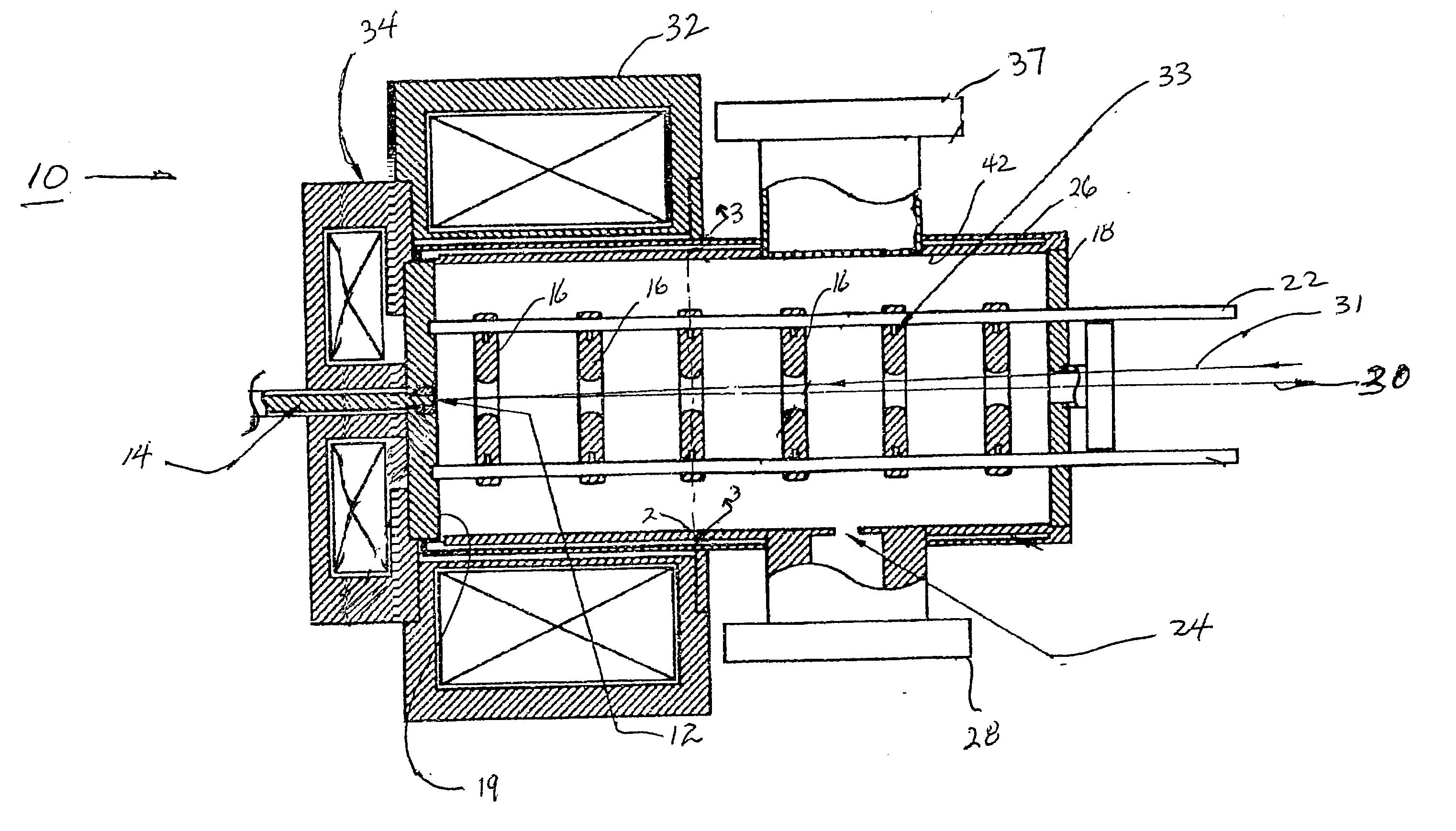
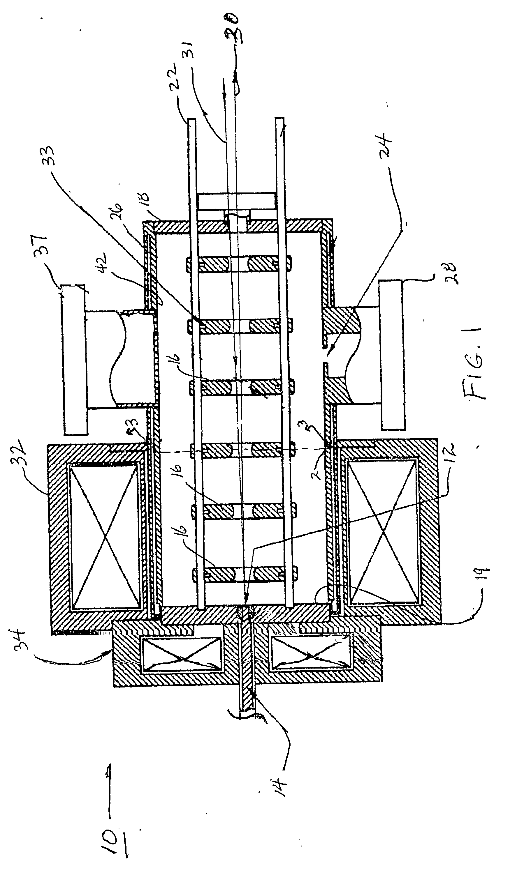
[0020] FIG. 1 shows a schematic diagram of the polarized electron PWT photoinjector 10 of the present invention.

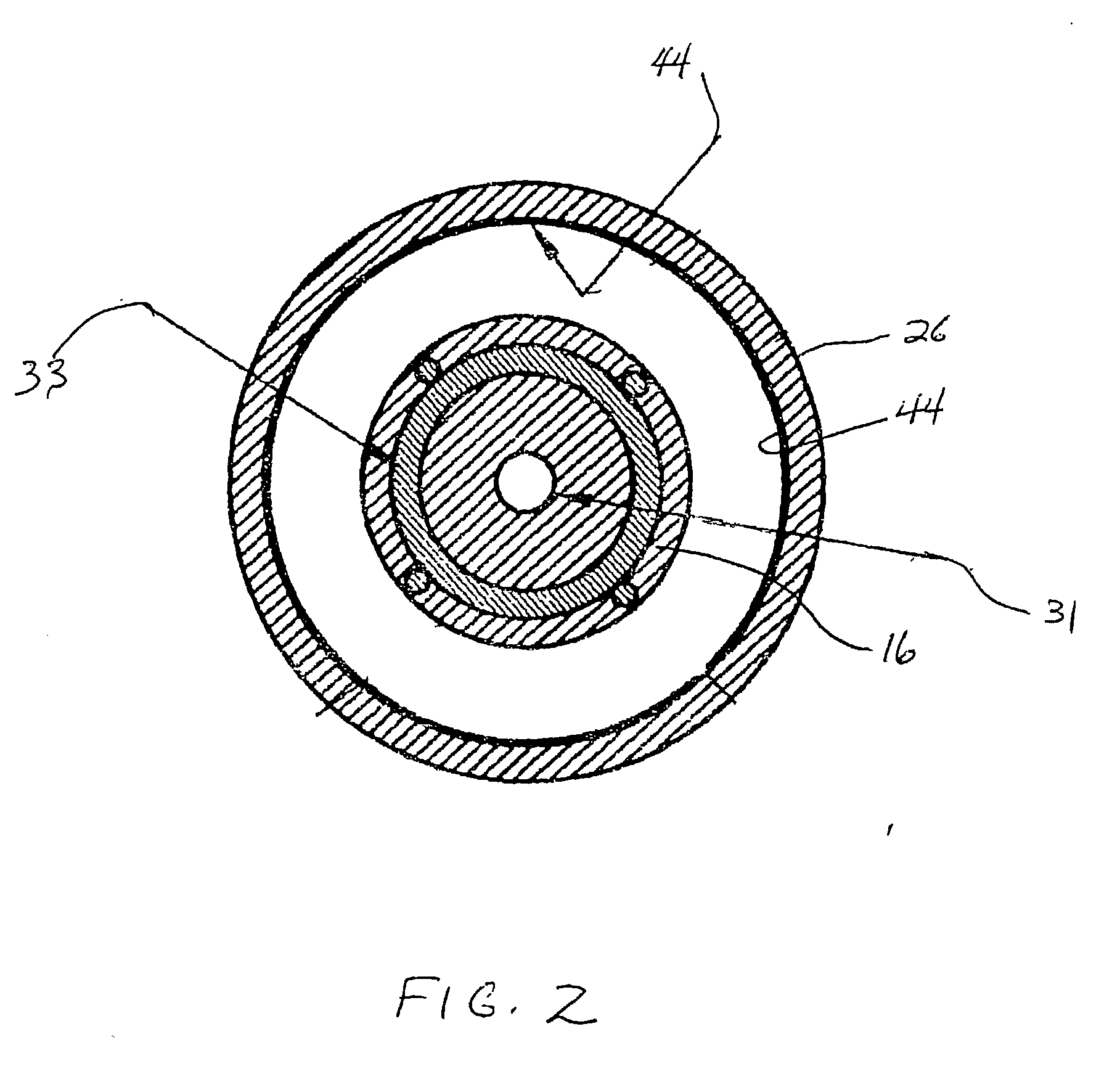
[0021] The integrated PWT photoelectron linear accelerator 10 which includes photocathode 12 is located directly inside the full accelerating structure and supported on demountable cathode assembly 14. The PWT linac 10 is a n-mode, standing-wave, linac structure which consists of a series of cylindrical disks 16 forming a disk assembly, each disk 16 being spaced half a wavelength apart, except for the first and last disks which are at a distance about a quarter wavelength from the end plates 18 and 19. The disk assembly is positioned within the tube, or tank, 26, and is supported by a water-carrying tube 22, tube 22 serving both to support and cool disks 16. A cooling channel 33 is provided to additionally cool the disks 16. Suspended along the axis of a large cylindrical tank, or tube, 26, the disk assembly defines a series of open cavities or cells. Unlike the convention...


PUM


Abstract

A photoelectron linear accelerator for producing a low emittance polarized electron beam. The linear accelerator includes a tube having an inner wall, the inner tube wall being coated by a getter material. A portable, or demountable, cathode plug is mounted within said tube, the surface of said cathode having a semiconductor material formed thereon.

Description

[0002] 1. Field of the Invention[0003] The present invention provides a photoelectron linear accelerator for producing a polarized electron beam with low emittance.[0004] 2. Description of the Prior Art[0005] Polarized electron beams are a principal investigative tool at a number of major accelerator centers. It has been demonstrated that polarized electrons will be extremely useful in electron position colliders. Current polarized electron beams for accelerators are generated by dc-biased electron guns that utilize gallium arsenide (GaAs) as the photocathode material. The relatively long pulse (on the order of nanoseconds) generated by these sources is rf chopped and bunched in the injector to derive the desired pulse structure, including microbunch number and temporal width, to match the accelerator and experiment requirements.[0006] The normalized rms transverse emittance of high charge rf-bunched beams is typically on the order of 10.sup.-4 m. Future colliders require an emittan...

Claims


Application Information

Patent Timeline
IPC IPC(8): H05H9/00
CPCH05H9/00
Inventor YU, DAVID U. L.CLENDENIN, JAMES E.KIRBY, ROBERT E.
Owner DULY RES
Why Eureka
Try Eureka