
Radiation detection

a technology of radiation detection and scintillator material, applied in the field of radiation detection, can solve the problems of low fluorescence efficiency, small photoemission amount, and inability to meet all these conditions at the same tim

Inactive Publication Date: 2004-05-06
JAPAN SCI & TECH CORP
View PDF2 Cites 6 Cited by
  • Summary
  • Abstract
  • Description
  • Claims
  • Application Information

AI Technical Summary

Benefits of technology

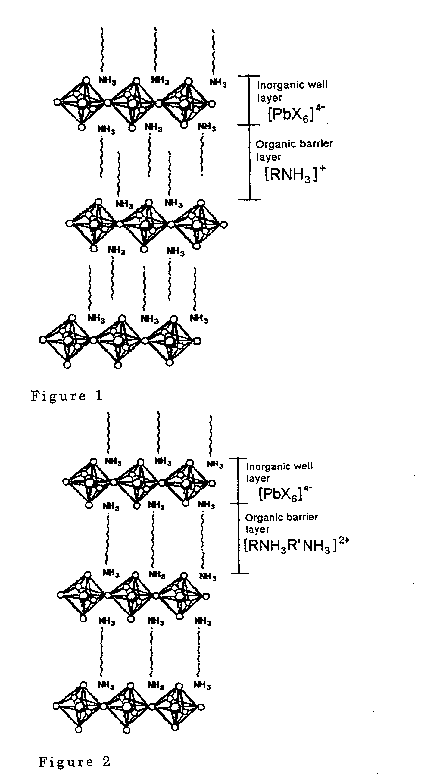
[0017] FIG. 2 is a schematic view of a laminar structure (low dimensional quantum well structure) of an organic-inorganic perovskite compound represented by (NH.sub.3--R'--NH.sub.3)MX.sub.4.

Problems solved by technology

Until now, however, no scintillator material was capable of satisfying all these conditions simultaneously.
On the other hand, although organic crystals such as anthracene or naphthalene had a fast response in nanosecond units, their fluorescence efficiency was low and photoemission amount was small, hence measurement precision was low and as their radiation resistance was low, they were not suitable for practical use.
Pigments, which are well known as exciton emission materials, have a low radiation resistance, and therefore exciton emission materials could not be used as scintillators in the prior art.
Further, it permits detection of short pulse ionizing radiations of nanosecond order which could not be measured by the scintillation counter of the prior art.
Secondly, it is easy to manufacture a scintillator.
Thirdly, an expensive photoreceiver is not required for radiation detection.

Method used


Image

  • Radiation detection
  • Radiation detection
  • Radiation detection

Examples


example 1

[0040] A laminar perovskite compound (C.sub.6H.sub.13NH.sub.3).sub.2PbI.su-b.4 was synthesized by reacting lead iodide PbI.sub.2 as a halogenated metal and C.sub.6H.sub.13NH.sub.3I as an organic amine halogenated hydroacid salt in a molar ratio of 1:2 in N,N'-dimethylformamide (reaction temperature: room temperature (20 degree C.), reaction time: 1 hour or more).

[0041] 1 g of this laminar perovskite compound was dissolved in 3 ml of acetone, and spin-coated on a silicon (Si) substrate of 2 cm angle using a Shimadzu Laboratories P / N 202-32016 (rotation speed: 5000 rpm, time: 30 seconds or more) to manufacture a scintillator (thickness of laminar perovskite compound 0.1 .mu.m). Here, a silicon substrate was used to avoid photoemission from the substrate.

[0042] FIG. 3 shows the radiation detection device used in this example. This device comprises a stainless steel cylinder of diameter approximately 50 cm, and comprises a window through which the radiation enters, a light receiving por...

example 2

[0047] The absorbed radiation amount was varied from 4.2.times.10.sup.6 Gy-1.5.times.10.sup.7Gy, and the relation between the absorbed radiation amount of the laminar perovskite compound and radiation intensity of the exciton photoemission (exciton photoemission amount) was investigated as in the case of Example 1. FIG. 5 shows the relation between the radiation intensity of the exciton photoemission and the absorbed radiation amount of (C.sub.6H.sub.13NH.sub.3)PbI.sub.4. This radiation intensity was computed from the peak (524.+-.0.5 nm) of the exciton photoemission shown in FIG. 4.

[0048] From FIG. 5, it is seen that this exciton photoemission amount decreases gradually as the absorbed radiation amount increases. Therefore, the radiation amount can be directly calculated from the photoemission amount. In other words, the radiation detection device of this invention can measure the radiation amount. Further, the fact that the exciton photoemission amount has this constant functional...

example 3

[0049] The scintillator manufactured in Example 1 was excited using a pulse electron beam of pulse width 1 picosecond accelerated to 30 MeV by a linear accelerator (LINAC) in a vacuum (approximately 10.sup.-6 Torr), and the time shift of the integrated intensity of the excited photoemission was measured. The photoreceptor was a streak camera (Yokohama Photonics Corporation, FESCA-200) having a time resolution of 260 femtoseconds. FIG. 6 shows the results. From analyzing this graph, the time constant of the decay of this photoemission was approximately 45 picoseconds.


PUM

PropertyMeasurementUnit
thicknessaaaaaaaaaa
diameteraaaaaaaaaa
wavelengthaaaaaaaaaa

Abstract

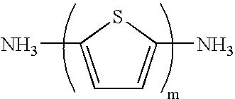
This invention relates to a radiation detection device for detecting ionizing beam discharges such as gamma rays, x-rays, electron beams, charged particle beams and neutral particle beams. Specifically, it relates to a radiation detection device which can measure radiations which exist for a very short time (of the order of subnanoseconds or less) from the appearance of photoemission to extinction. It is an object of this invention to provide a radiation detection device using a perovskite organic-inorganic hybrid compound as a scintillator, the formula of this compound being (R<1>-NR<11>3)2MX4 or (R<2>=NR<12>2)2MX4, or alternatively, (NR<13>3-R<3>-NR<13>3)MX4 or (NR<14>2=R<4>=NR<14>2)MX4 (in the formula, R<1 >is a monovalent hydrocarbon group which may contain a heterocyclic ring and may be substituted by halogen atoms, R<2 >is a divalent hydrocarbon group which may contain a heterocyclic ring and may be substituted by halogen atoms, and may be cyclic, R<3 >is a divalent hydrocarbon group which may contain a heterocyclic ring and may be substituted by halogen atoms, R<4 >is a tetravalent hydrocarbon group which may contain a heterocyclic ring and may be substituted by halogen atoms, R<11>-R<14 >may be identical or different, and may be hydrogen atoms or alkyl groups having two or more atoms, M is a Group IVa metal, Eu, Cd, Cu, Fe, Mn or Pd, and X is a halogen atom). This radiation detection device can quantify the radiation amount of the detected radiation.

Description

[0001] This invention relates to a radiation detection device for detecting ionizing beam discharges such as gamma rays, x-rays, electron beams, charged particle beams and neutral particle beams. Specifically, it relates to a radiation detection device which can measure radiation beams which exist for a very short time (of the order of subnanoseconds or less) from the appearance of photoemission to extinction.PRIOR ART[0002] To detect or measure ionizing beams, a scintillation counter is used. In recent years, it has become necessary to measure very short pulse radiations of the order of nanoseconds in a radiation field.[0003] The scintillator must have the following functions: (i) High scintillation efficiency and large photoemission amount (ii) Short photoemission appearance time and decay time (iii) High resistance to radiation (iv) It should permit measurement of the radiation amount. Until now, however, no scintillator material was capable of satisfying all these conditions sim...

Claims


Application Information

Patent Timeline
Patent Type & Authority Applications(United States)
IPC IPC(8): C09K11/00G01T1/20C09K11/06G01T1/00G01T1/202
CPCG01T1/2018G01T1/2006H10K85/50
Inventor SHIBUYA, KENGOKOSHIMIZU, MASANORITAKEOKA, YUKOASAI, KEISUKE
Owner JAPAN SCI & TECH CORP
Learn More