If a compound for a rare-earth bonded magnet (which will be simply referred to herein as a "compound") is obtained by mixing the powder of such a shape and a binder together, the compound will exhibit poor flowability during an
injection molding process, for example.
Thus, such a compound may need to be compacted at a higher temperature and / or at a higher pressure, the types and applications of resins to be used may be limited, or the content of the magnet powder may be limited to ensure sufficient flowability.
Also, it has been difficult to obtain a bonded magnet having a complex shape or a bonded magnet to fill a small gap (e.g., with a width of 2 mm) as in an IPM (interior permanent magnet) type motor including a magnet embedded rotor as disclosed in Japanese Laid-Open Publication No. 11-206075.
Furthermore, in a compound including the conventional rapidly solidified magnet powder (e.g., the MQ powder), the magnet powder is easily oxidized in air, the properties of the magnet powder itself deteriorate due to the heat during an
injection molding process, and the
resultant bonded magnet may exhibit insufficient magnetic properties.
Accordingly, when a bonded magnet is made of a compound including the conventional rapidly solidified magnet powder, the compacting temperature is limited to minimize the oxidation to be caused by the heat during the molding process.
Thus, during the manufacturing process, the magnet powder in the compound may be oxidized and the
resultant magnetic properties may deteriorate.
When the magnet powder is exposed in some areas in this manner,
corrosion easily advances from those areas.
This problem is particularly noticeable when the wettability between the resin and the magnet powder is poor.
Specifically, the conventional rapidly solidified magnet powder has a small
aspect ratio, and is hard to mix uniformly in the compound preparing process step.
Thus, in the
resultant compound, the wettability between the resin and the magnet powder may be poor enough to
expose the magnet powder particles here and there.
As a result, the magnet powder in the resultant compound is easily oxidizable.
Thus, the magnetic properties (e.g.,
coercivity H.sub.cJ) thereof are inferior to those of the conventional rapidly solidified magnet powder (such as the MQ powder).
Accordingly, it is difficult to make a bonded magnet with sufficient magnetic properties from a compound including only the
nanocomposite magnet powder as its magnet powder.
Consequently, it has been difficult so far to obtain a bonded magnet with excellent magnetic properties while totally eliminating the problems of the compound including the conventional rapidly solidified magnet powder.
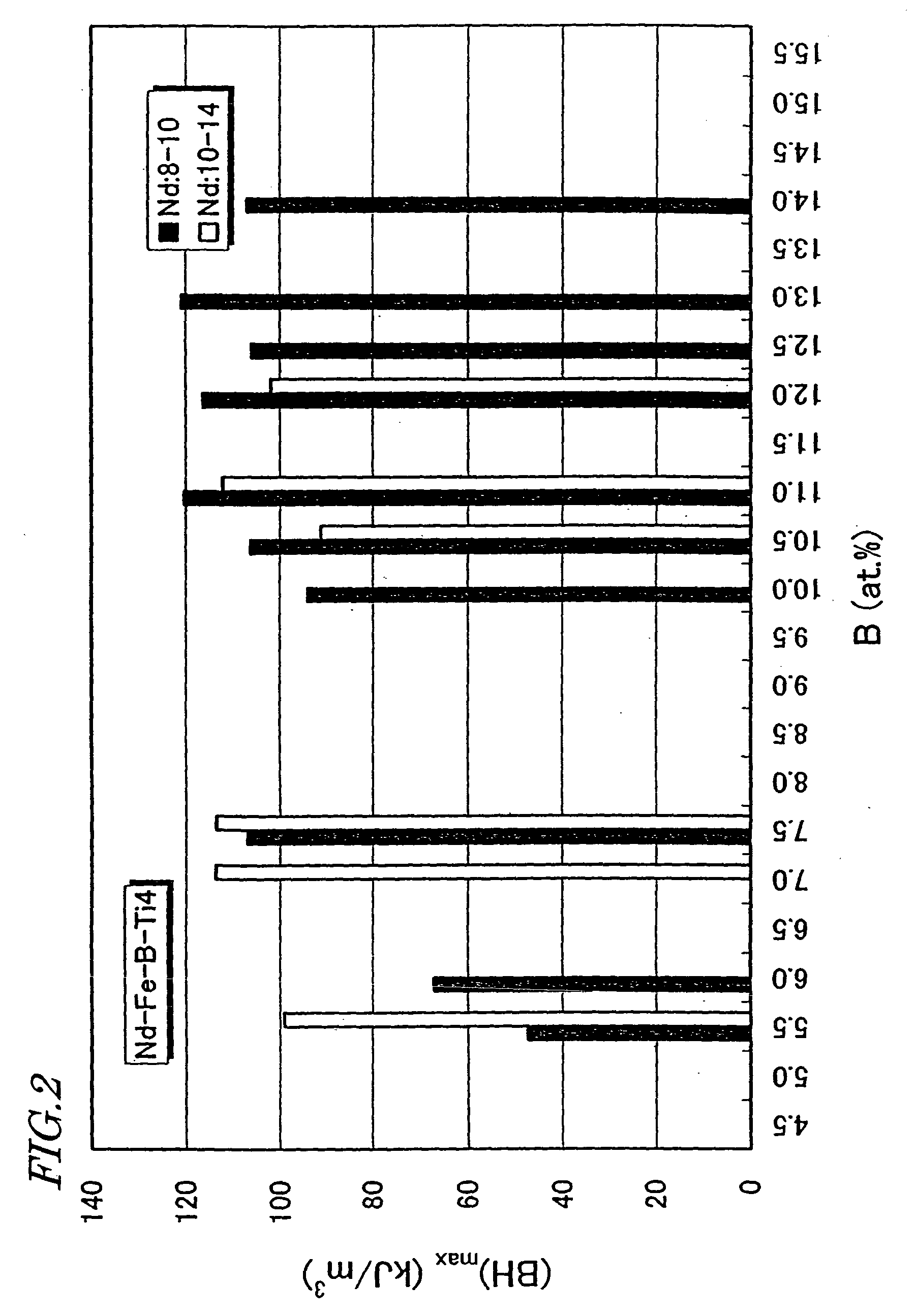
The Ti-containing
nanocomposite magnet powder can easily achieve a
coercivity H.sub.cJ of about 480 kA / m or more, which has been hard to achieve for the conventional nanocomposite magnet powder.
Furthermore, since the magnet powder itself exhibits excellent anticorrosiveness, the magnet performance deteriorates extremely slightly even when the thermosetting process is carried out in the air.
Thus, the smaller the particle size, the morn significantly the magnetic properties are deteriorated due to the oxidation of the surface of the powder particles.
In the conventional rapidly solidified magnet powder, however, particles with relatively
small particle sizes exhibit inferior magnetic properties as described above.
As a result, the productivity of the compound increases and the manufacturing cost decreases.
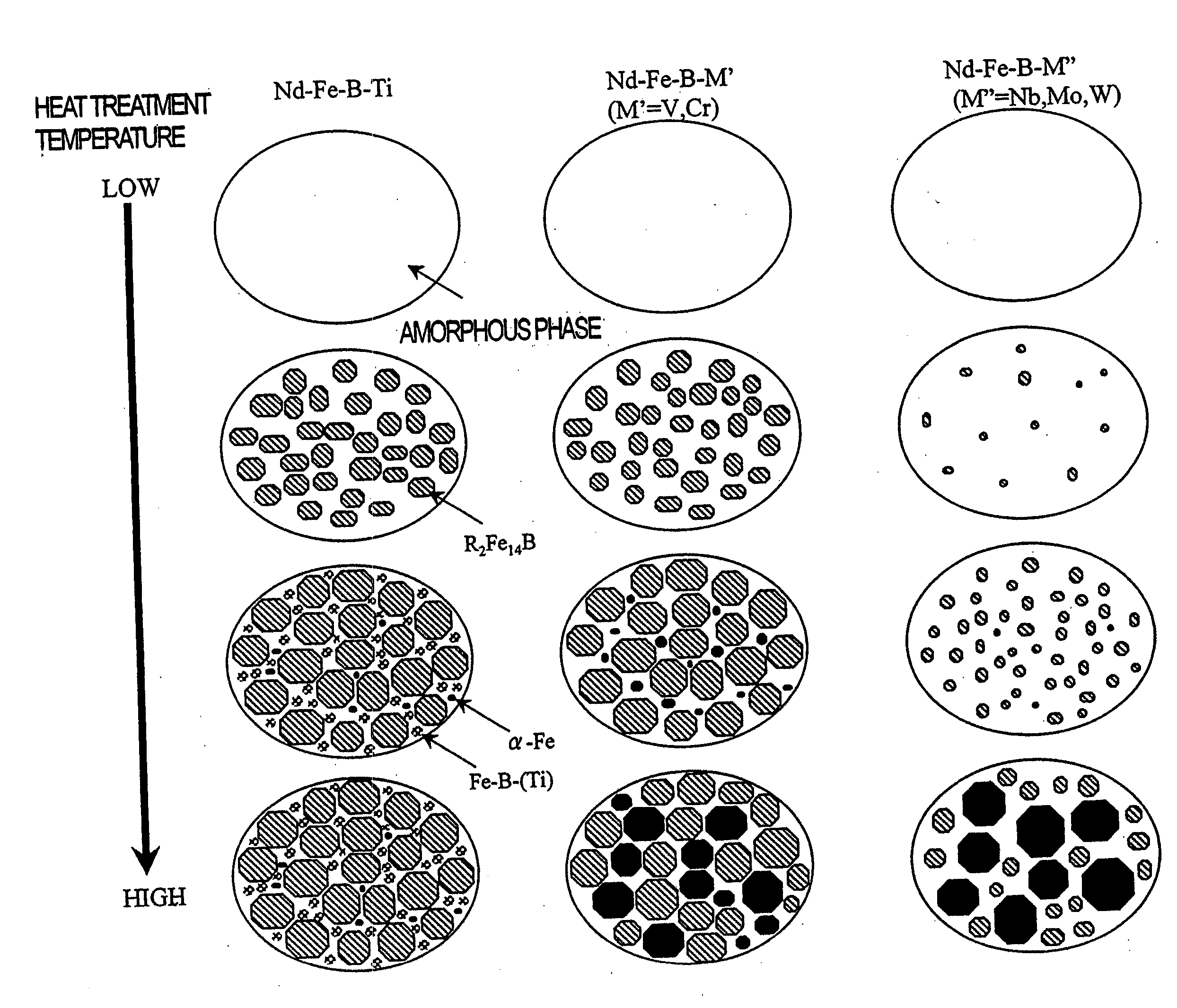
Accordingly, when the rapidly solidified alloy is thermally treated to be crystallized, the .alpha.-Fe phase with soft magnetic properties will have grown excessively and no excellent magnetic properties (e.g., H.sub.cJ and loop squareness, in particular) will be achieved.
This is because if the roller
surface velocity is lower than about 4 m / s, then the R.sub.2Fe.sub.14B compound phase, included in the rapidly solidified alloy, will have excessively large crystal grains.
In that case, the R.sub.2Fe.sub.14B compound phase will further increase its grain size when thermally treated, thus possibly deteriorating the resultant magnetic properties.
Thus, when the alloy is heated and crystallized after that, the .alpha.-Fe phase will increase its grain size excessively.
Once soft magnetic phases such as the .alpha.-Fe phase have grown too much, the magnetic properties of the alloy deteriorate significantly, thus making it virtually impossible to produce a quality bonded magnet out of such an alloy.
Thus, when that alloy is heated and crystallized after that, the .alpha.-Fe phase will further grow to deteriorate the magnetic properties of the alloy seriously.
Unlike the situation where Ti is added, the .alpha.-Fe phase grows rapidly and increases its grain size excessively.
As a result, the exchange interactions among the constituent phases weaken and the loop squareness of the demagnetization curve deteriorates significantly.
The additive V or Cr cannot minimize the heat-treatment-induced
grain growth sufficiently, either, and deteriorates the loop squareness of the demagnetization curve.
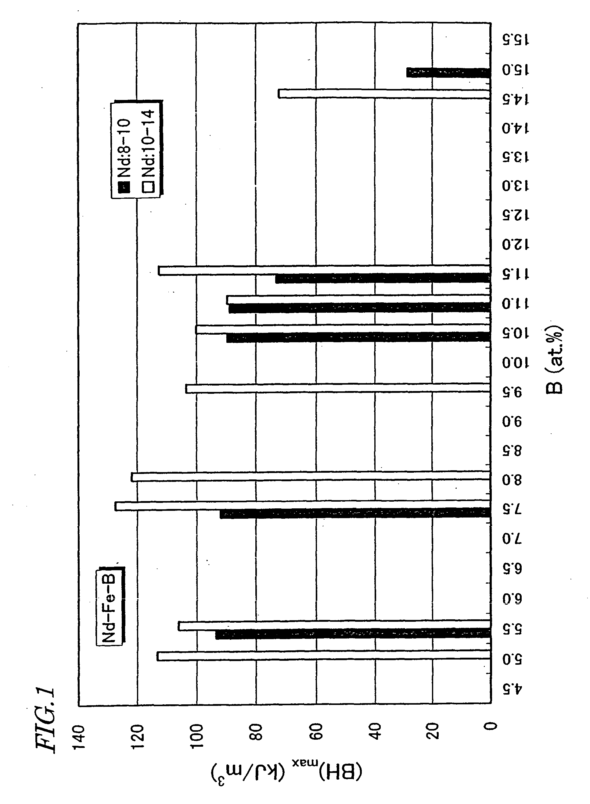
In the prior art, however, if B is added that much, then not just non-magnetic amorphous phases but also an .alpha.-Fe phase and / or a soft magnetic Nd.sub.2Fe.sub.23B.sub.3 phase will grow preferentially to have excessively large grain sizes when the rapidly solidified alloy is thermally treated and crystallized.
Also, if the chill roller is made of a material other than Cu or Fe, the resultant rapidly solidified alloy cannot peel off the chill roller easily and might be wound around the roller.
Among these rapid cooling techniques, the
strip casting method results in a relatively low
cooling rate, i.e., about 10.sup.2.degree. C. / s to about 10.sup.5.degree. C. / s.
Consequently, the desired
metal structure cannot be obtained.
If the heat treatment temperature is lower than about 550.degree. C., then a lot of amorphous phases may remain even after the heat treatment and the resultant
coercivity may not reach the desired level depending on the conditions of the rapid cooling process.
On the other hand, if the heat treatment temperature exceeds about 850.degree. C., the
grain growth of the respective constituent phases will advance too much, thus decreasing the
remanence B.sub.r and deteriorating the loop squareness of the demagnetization curve.
That is to say, the heat treatment for
crystallization is not an indispensable process.
In addition, even though the heat treatment is carried out at lower temperatures than the conventional process, the magnetic properties are still improvable sufficiently.
Nevertheless, if the average crystal grain size of these phases is less than about 1 nm, then a high coercivity cannot be achieved.
When such a phenomenon occurs, the magnetic properties deteriorate significantly in a nanocomposite magnet powder, in particular.
Thus, the magnet powder is not oxidizable so easily even when exposed to the air during the heat treatment process or any other process.
In addition, a
strip casting process or an atomization process cannot be adopted in that case, even though these processes count among most cost-effective techniques in various
melt quenching processes.
As a result, the manufacturing cost of the magnet powder increases unintentionally.
However, if more than about 50% of Fe is replaced with T (i.e., m>0.5), then a high
remanence B.sub.r of about 0.7 T or more cannot be obtained.
Thus, even while a bonded magnet is produced from this magnet powder (e.g., while a compound is being prepared and / or thermally cured), the magnet powder is not oxidized easily.
Furthermore, the conventional rapidly solidified magnet powder has too low
oxidation resistance to be applied to making an injection-molded bonded magnet by performing the process step of compounding the powder with a resin binder or molding the mixture at a temperature of about 250.degree. C. to about 300.degree. C.
The conventional rapidly solidified magnet powder includes a relatively large amount of rare-earth element R and is easily oxidizable.
Thus, the smaller the size of powder particles, the more significantly the magnetic properties thereof deteriorate due to the oxidation of the powder particles at the surface.
That is to say, a quality compact of a
high density cannot be obtained.
In particular, compounds can be obtained relatively easily by using high-melting resins with
softening points of about 180.degree. C. or more (e.g., nylon 6 and polyphenylene
sulfide), which have been difficult to use at an
industrial scale.
Furthermore, when the Ti-containing nanocomposite magnet powder is used, the compactibility and flowability are improvable.
Accordingly, high-
viscosity resins, which have been difficult to use in the prior art, may also be used.
Furthermore, the magnet powder is not oxidizable easily.
However, if the magnet powder percentage is increased excessively, then the resin binder for binding the magnet powder particles together tightly enough might be in an insufficient amount, thus possibly decreasing the
mechanical strength of the resultant bonded magnet or dropping the magnet powder particles during the use of the magnet.
Also, the compound can be molded into a complex shape, which has been difficult to realize when a compound including the conventional rapidly solidified magnet powder is used.
At this point in time, however, the bonded magnet 210 is still a powder compact of the compound and the thermosetting resin included in the compound has not cured yet.
Thus, even if the thermosetting process is carried out in the air, the resultant magnet properties deteriorate only slightly.

