Chemical reaction circuit for cell-free protein synthesis

a cell-free protein and reaction circuit technology, applied in the field of cell-free protein synthesis, can solve the problems of inability to carry out the transmission of light frequently conducted in the chemical field, product as high as tens of thousands of yen per piece, and product cracking, etc., and achieve the effect of relatively easy embedding into a microchip

Inactive Publication Date: 2004-07-29
JAPAN SCI & TECH CORP
View PDF0 Cites 5 Cited by
  • Summary
  • Abstract
  • Description
  • Claims
  • Application Information

AI Technical Summary

Benefits of technology

[0016] a unidirectional valve for preventing reverse flow of a reagent and
[0020] a unidirectional valve for preventing reverse flow of a reagent and
[0080] (b) a unidirectional valve for preventing reverse flow of a reagent and
[0086] In this case, exemplified as the separation device are various means such as electrophoresis, gel column, filter paper, ultrafiltration membrane and the like. Of them, the ultrafiltration membrane is preferable since the kind of the membrane can be appropriately selected depending on the separation range, and embedding into a micro chip is also relatively easy.

Problems solved by technology

However, chemical IC obtained by methods based on such conventional photolithography and etching technologies uses silicon or glass as a substrate, therefore, when used as an analysis equipment or chemical reaction circuit, has various problems.
For example, a silicon wafer is opaque, and resultantly has problems that detection by transmitted light frequently conducted in the chemical field cannot be carried out, and the wafer tends to be cracked.
Production of chemical IC by these methods needs specific apparatuses and equipments and such as for working in a clean room and the like, and the resulted product is as extremely expensive as tens of thousands of yen per piece in the case of a micro electrode on a glass substrate.
Therefore, though low cost, disposable use and the like are expected, use in a general chemical experiment is not realistic under actual conditions.
Further, in method of producing chemical IC in which a channel is formed by photolithography and etching technologies, formation of a complicated three dimensional structure is actually impossible, and a valve, pump, reaction vessel, condenser and the like cannot be formed on chemical IC.
Further, photolithography and etching technologies are not suitable for formation of chemical IC as used in a biochemical experiment, since a high temperature treatment and chemical treatment are necessary in such technologies.
However, in a live cell, various self-defense mechanisms by the cell self act, and additionally, it is necessary, after cultivation of a protein containing an introduced gene, to break the cell and separate and purify the intended protein, therefore, there are a lot of constrains such as complicated synthesis operations and the like.
However, in the case of such cell-free protein synthesis method, there is a problem that, when conducted in batch-mode, the reaction terminates in about 2 hours, and consequently, the amount of the resulting protein is smaller for the amount of a reagent used.
Further, such systems are also expected to be applied to various fields such as order made medical care and intra-body embedded devices and the like for which limited production of diversified products is inevitable.

Method used


Image

  • Chemical reaction circuit for cell-free protein synthesis
  • Chemical reaction circuit for cell-free protein synthesis
  • Chemical reaction circuit for cell-free protein synthesis

Examples


example 1

Construction of Chemical Reaction Circuit for Cell-Free Protein Synthesis

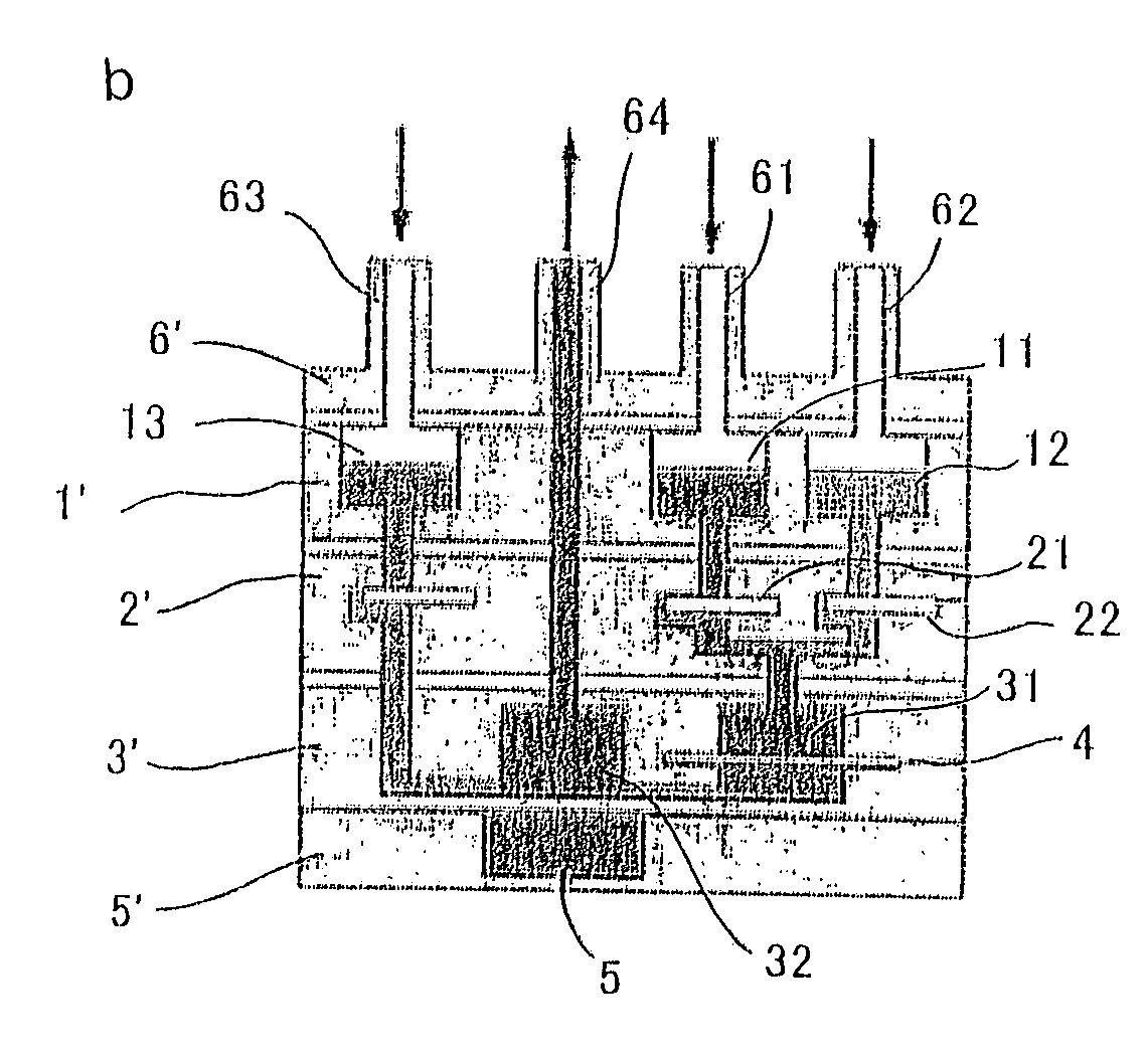
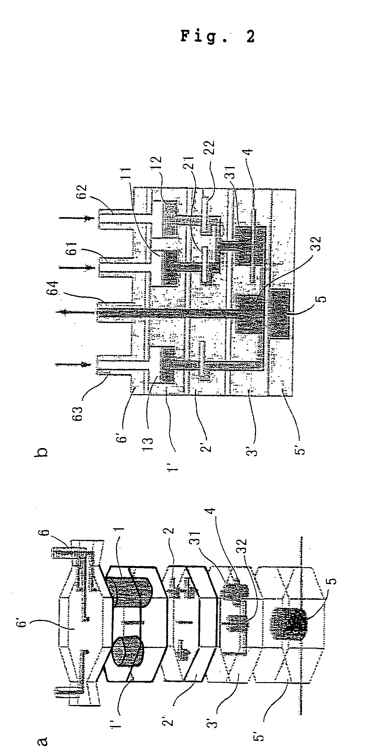
[0107] According to the hybrid micro stereolithography suggested by the present inventors (JP-A Nos. 7-329188, 2001-158050, 2001-157662, 2001-158000 and the like), a connector chip (6) as a micro chip having a connector part (6), a reservoir chip (1') as a micro chip having a reagent storage tank (1), a valve chip (2') as a micro chip having a unidirectional valve (2), a reactor chip (3') as a micro chip having a reaction tank (31) and a product storage tank (32), and a sensor chip (5') as a micro chip having a photo sensor (5), were shaped. A silicon membrane was incorporated into the valve chip (2'), an ultrafiltration membrane (MICROCON YM100, manufactured by Miropore) was integrated into the reactor chip (3'), and an avalanche photo diode was integrated into the sensor chip (5). Each micro chip was made as an octagon of 14 mm and a thickness of 2 to 5 mm excepting the connector chip (6). Further, the diamet...

example 2

Protein Synthesis Test

[0109] A test of protein synthesis was conducted using the chemical reaction circuit for cell-free protein synthesis as constructed in Example 1. The intended protein was firefly luminescence enzyme luciferase detectable easily.

[0110] FIG. 4 shows a schematic view of a chemical reaction circuit system for cell-free protein synthesis used for synthesis of luciferase.

[0111] (a) The feeding connectors (51, 52, 53) on the connector chip (5) of the chemical reaction circuit for cell-free protein synthesis as constructed in Example 1 were connected to the discharge side of a roller pump (8), and a discharge connector (54) was connected to the waste liquid tank (8). Into a first storage tank (11) on the reservoir chip (1') was introduced a reagent A (containing amino acid, ATP, GTP, DNA) composed of 3 .mu.l of ultra pure water, 1.25 .mu.l of Amino Acid Mixture 1 (manufactured by Promega, L1020 E. coli S30 Extract System for Circular DNA kit), 1.25 .mu.l of Amino Acid ...


PUM

PropertyMeasurementUnit
heightaaaaaaaaaa
thicknessaaaaaaaaaa
thicknessaaaaaaaaaa

Abstract

A chemical reaction circuit for cell-free protein synthesis characterized by, as a chemical reaction circuit for synthesizing a protein, having at least one reagent tank for storing a reagent for the protein synthesis and / or a reagent for detecting a product, a unidirectional valve for preventing the reverse-flow of the reagent(s), and a reaction tank connected to the reagent tank(s) via the unidirectional valve. This circuit is usable as a micro reactor whereby cell-free protein synthesis can be carried out.

Description

[0001] The present invention relates to a chemical reaction circuit for cell-free protein synthesis useful as a portable system for conducting cell-free synthesis of a protein. More specifically, the present invention relates to a chemical reaction circuit for cell-free protein synthesis enabling cell-free synthesis of a protein using a trace amount of reagent.[0002] Recently, intending high speed, high efficiency and integration of chemical experiments or super miniaturizing of analysis equipments, there are active studies on "chemical IC" or "biochemical IC" having inside a chemical reaction circuit for conducting basic chemical operations such as reaction, separation, extraction, detection and the like.[0003] Chemical IC has various advantages as compared with conventional devices such as capability of measurement and analysis with a small amount of sample, capability of carrying, realization of low cost, capability of disposal and the like, and particularly has high usefulness i...

Claims


Application Information

Patent Timeline
Patent Type & Authority Applications(United States)
IPC IPC(8): C12P21/00C12P21/02
CPCC12P21/02C12P21/00
Inventor IKUTA, KOJI
Owner JAPAN SCI & TECH CORP
Why Eureka
Try Eureka