
Spectrometric using broadband filters with overlapping spectral ranges

a broadband filter and spectrometer technology, applied in the field of spectrometers or spectroradiometers, can solve the problems of poor signal to noise ratio, low throughput, and disadvantages of conventional spectrometers known to the applicant, and achieve the effect of better filter choi

Inactive Publication Date: 2004-08-05
CSIR
View PDF24 Cites 27 Cited by
  • Summary
  • Abstract
  • Description
  • Claims
  • Application Information

AI Technical Summary

Benefits of technology

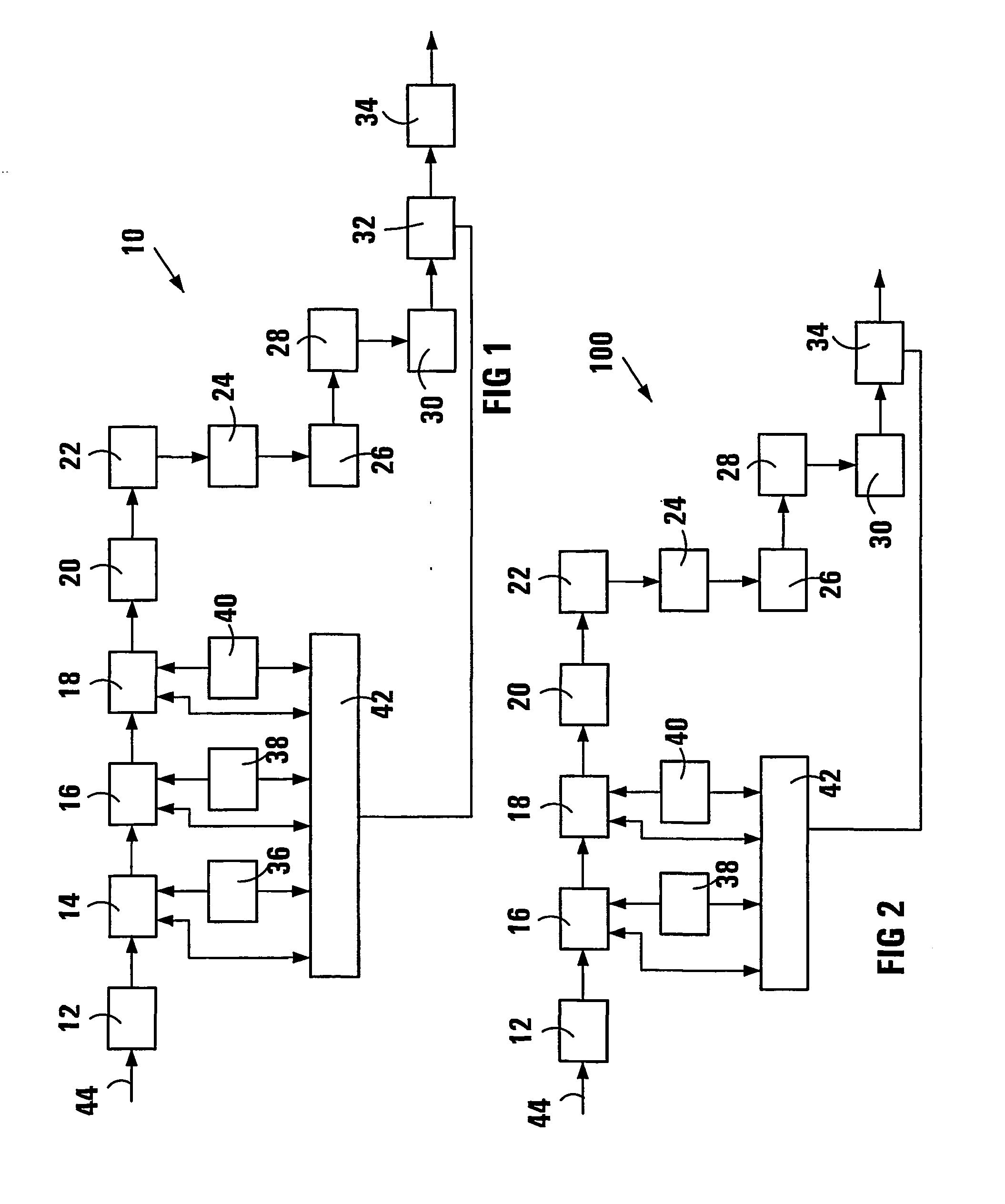
[0012] The filter arrangement may include a filter set with a plurality of unique and individual broadband filters or filter areas. Preferably, in this case, all the broadband filters or filter areas are linearly independent, i.e. the transmission of any one broadband filter or filter area is preferably not a multiple of the transmission of any other broadband filter or filter area. In one embodiment of the invention, the filter arrangement includes at least two filter sets arranged one in front of the other to provide broadband filter combinations. Most preferably, the filter arrangement includes only two filter sets, to ensure a high throughput through the filter arrangement, whilst retaining the advantage of reduced cost.
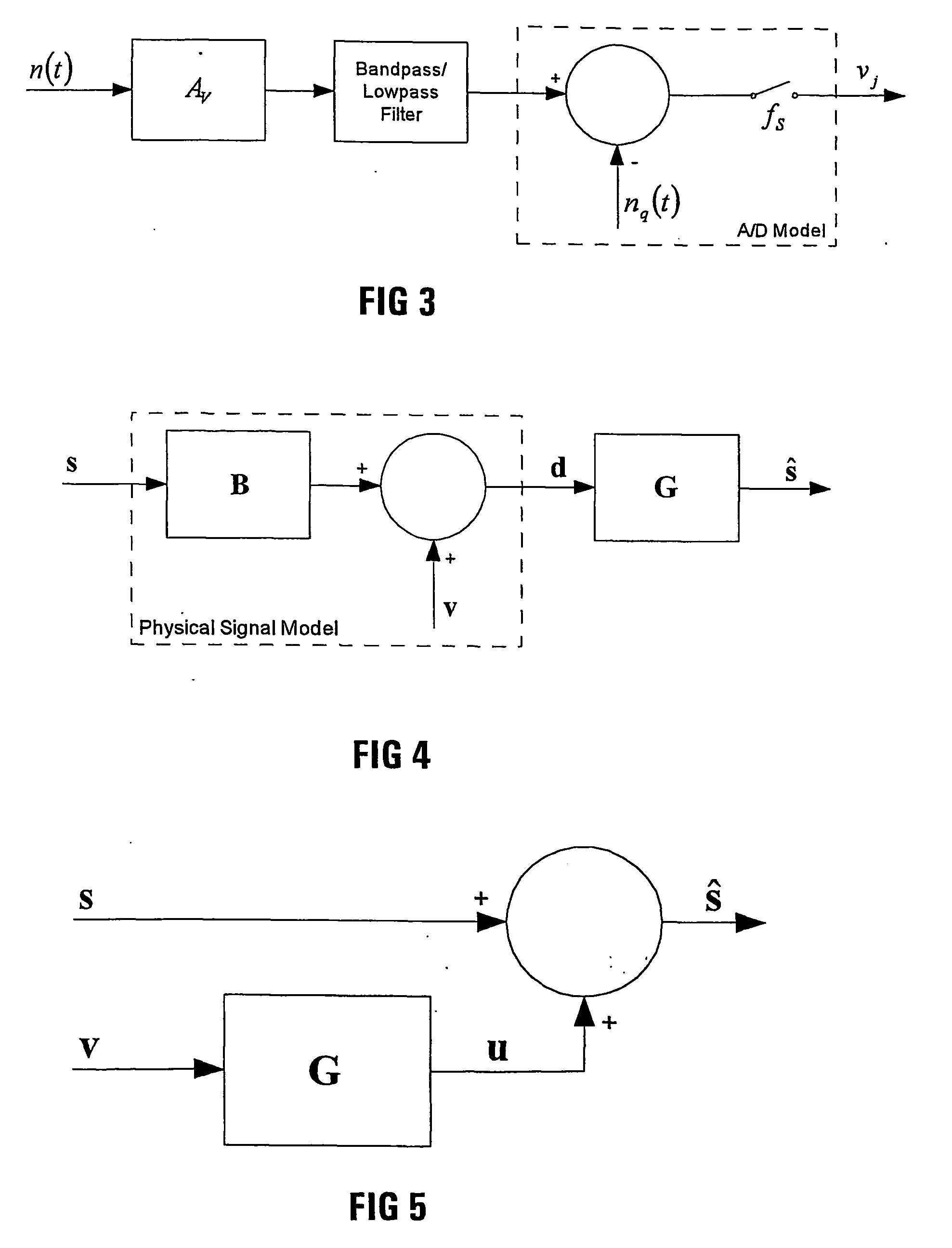
[0025] B=U.SIGMA.V', the singular value decomposition of B, where U and V are J.times.N and N.times.N orthogonal matrices, the matrix .SIGMA. is a N.times.N diagonal matrix containing the singular values of B in descending order, i.e. .SIGMA.=diag{.gamma..sub.1, . . . ,.gamma..sub.N}, .gamma..sub.1.gtoreq..gamma..sub.2 . . . .gtoreq..gamma..sub.N.gtoreq.0, and r is an integer in the range 1<r.ltoreq.N selected to minimize the measurement error.
[0034] B=U.SIGMA.V', the singular value decomposition of B, where U and V are J.times.N and N.times.N orthogonal matrices, the matrix .SIGMA. is a N.times.N diagonal matrix containing the singular values of B in descending order, i.e. .SIGMA.=diag{.gamma..sub.1, . . . ,.gamma..sub.N}, .gamma..sub.1.gtoreq..gamma..sub.2 . . . .gtoreq..gamma..sub.N.gtoreq.0, and r is an integer in the range 1<r.ltoreq.N selected to minimize the measurement error.

Problems solved by technology

The conventional spectrometric devices known to the Applicant all suffer from inherent disadvantages.
Thus, a spectrometer using narrow band optical filters or prisms or gratings suffers from a poor signal to noise ratio and low throughput.
Fourier Transform Spectrometers, such as the Fourier Transform Infra-Red (FTIR) spectrometer, although possessing a multiplex advantage, and having a high throughput, are very expensive and not robust, requiring high tolerance components.
As will be appreciated, this makes it very difficult to build a Fourier Transform Spectrometer for use in the visual light spectrum.
Furthermore, a Fourier Transform Spectrometer suffers from a field of view dependent wavenumber shift or phase difference among the different pixels in the field of view.
A spectrometer using an acousto-optical tunable filter (AOTF) suffers from the disadvantage that the power of the radio frequency used to set up the acoustic wave in the crystal must be limited to inhibit unpredictable inter-modulation.
An AOTF spectrometer is costly to build and a crystal for use in the 8 to 12 .mu.m spectral radiation range has not been identified.

Method used


Image

  • Spectrometric using broadband filters with overlapping spectral ranges
  • Spectrometric using broadband filters with overlapping spectral ranges
  • Spectrometric using broadband filters with overlapping spectral ranges

Examples


example 2

[0216] In this example one thin film filter is used per measurement. The cosine function set described earlier has been used as a design target for the thin film transmissions. The parameters used for this spectrometer are listed in Table 67. The Essential Macleod V8.03e software was used to design the thin film filters.

8TABLE 7 Parameters used in the example N Number of spectral bands. 20 J Number of measurements used to 20 estimate the spectrum. .lambda..sub.L , .lambda..sub.U Upper and lower operational wavelength. 600-800 nm .DELTA..lambda. Wavelength resolution. 10 nm f.sub.s Sampling frequency 100 c / .mu.m Q Over-sampling factor 4 .tau..sub.L1 Transmission of collecting optics. 0.95 .tau..sub.L2 Transmission of focusing optics. 0.95 .tau..sub.F(.lambda.) Spectral band-pass filter. 0.95 T Radiometer throughput. 1 R(.lambda.) Detector responsivity (V / W). 1 A.sub.V Detector Pre-amp voltage gain (V / V). 1 .alpha. Transmission function offset 0.5 .beta. Transmission function swing 0....


PUM

PropertyMeasurementUnit
wavelengthsaaaaaaaaaa
wavelengthaaaaaaaaaa

Abstract

The invention provides a spectrometer (10) which includes a filter arrangement (16,18), in addition to any option filters (20) for limiting an operational wavelength range of the spectrometer, the filter arrangement (16,18) comprising a plurality of broadband optical filters or broadband optical filter areas each of known transmission and being located or selectively locatable in a path of collected incident spectral radiation (44). The spectrometer further includes at least one detector (24) arranged to measure the spectral radiation passing through at least one of the broadband filters located in the path of collected incident spectral radiation, and signal-processing means (34) for recovering the spectrum of the collected spectral radiation from measurements by the detector (24).

Description

[0001] THIS INVENTION relates to spectrometric devices. In particular, it relates to a spectrometer or spectro-radiometer or the like devices, and to a method of recovering a signal.[0002] The conventional spectrometric devices known to the Applicant all suffer from inherent disadvantages. Thus, a spectrometer using narrow band optical filters or prisms or gratings suffers from a poor signal to noise ratio and low throughput. Fourier Transform Spectrometers, such as the Fourier Transform Infra-Red (FTIR) spectrometer, although possessing a multiplex advantage, and having a high throughput, are very expensive and not robust, requiring high tolerance components. Thus, the distance that the mirror moves relative to the beam splitter of a Fourier Transform Spectrometer is very small, in the order of nanometers, particularly if the spectrometer is intended for use in the visual light spectrum. As will be appreciated, this makes it very difficult to build a Fourier Transform Spectrometer ...

Claims


Application Information

Patent Timeline
Patent Type & Authority Applications(United States)
IPC IPC(8): G01J3/12G01J3/28G01J3/51
CPCG01J3/0235G01J3/12G01J3/28G01J2003/123G01J3/51G01J3/524G01J2003/1217G01J3/462
Inventor GONCALVES, DUARTE PAULO DA SILVA
Owner CSIR
Learn More