
Surface modification of porous metal substrates

Active Publication Date: 2004-10-07
INTELLIGENT ENERGY INC
View PDF20 Cites 13 Cited by
  • Summary
  • Abstract
  • Description
  • Claims
  • Application Information

AI Technical Summary

Problems solved by technology

However, the amount of energy that can be stored in storage or rechargeable batteries is insufficient to meet the need of certain applications.
Merely providing compressed hydrogen is not always a viable option, because of the substantial volume that even a highly compressed gas occupies.
Furthermore, there are safety issues involved with the handling and storage of hydrogen in the compressed gas form or in the liquid form.
Methods such as water gas shift and preferential oxidation are used to reduce the CO concentrations to acceptable levels of no more than 50 parts per million, but increase the complexity of the system.
Commercial hydrogen separation membranes are unsupported and are tubular in nature.
The separation membranes are generally limited to operating temperatures below 450.degree. C. due to the sealing techniques used, which is inherent to tubular configurations, and are generally costly.
The problem with porous ceramic supports is that the adherence of a metallic membrane to a nonmetallic ceramic substrate is a major problem, particularly when the supported membrane is exposed to thermal cycling between room temperature and elevated temperatures of no less than 400.degree. C.
The synthesis and sintering process during the manufacture of the metal substrates does not allow for pore size and porosity to be varied independent of one another.
In addition, the surface of metal substrates is relatively rough.
Typically, techniques used to smoothen the surface, such as shot peening, results in pore closure and consequently decreases porosity and cause `pitting` of the surface which can increase surface roughness.
They have higher thermal conductivities than ceramics and therefore result in high heat transfer rates.
In general, the forming a thinner membrane saves costs and materials.
Additionally, if the membrane is applied in excess of about 20 microns it can lead to a process inefficiencies and higher costs, particularly when the hydrogen separation device is part of the fuel processor for producing hydrogen.

Method used


Image

  • Surface modification of porous metal substrates
  • Surface modification of porous metal substrates

Examples


Embodiment Construction

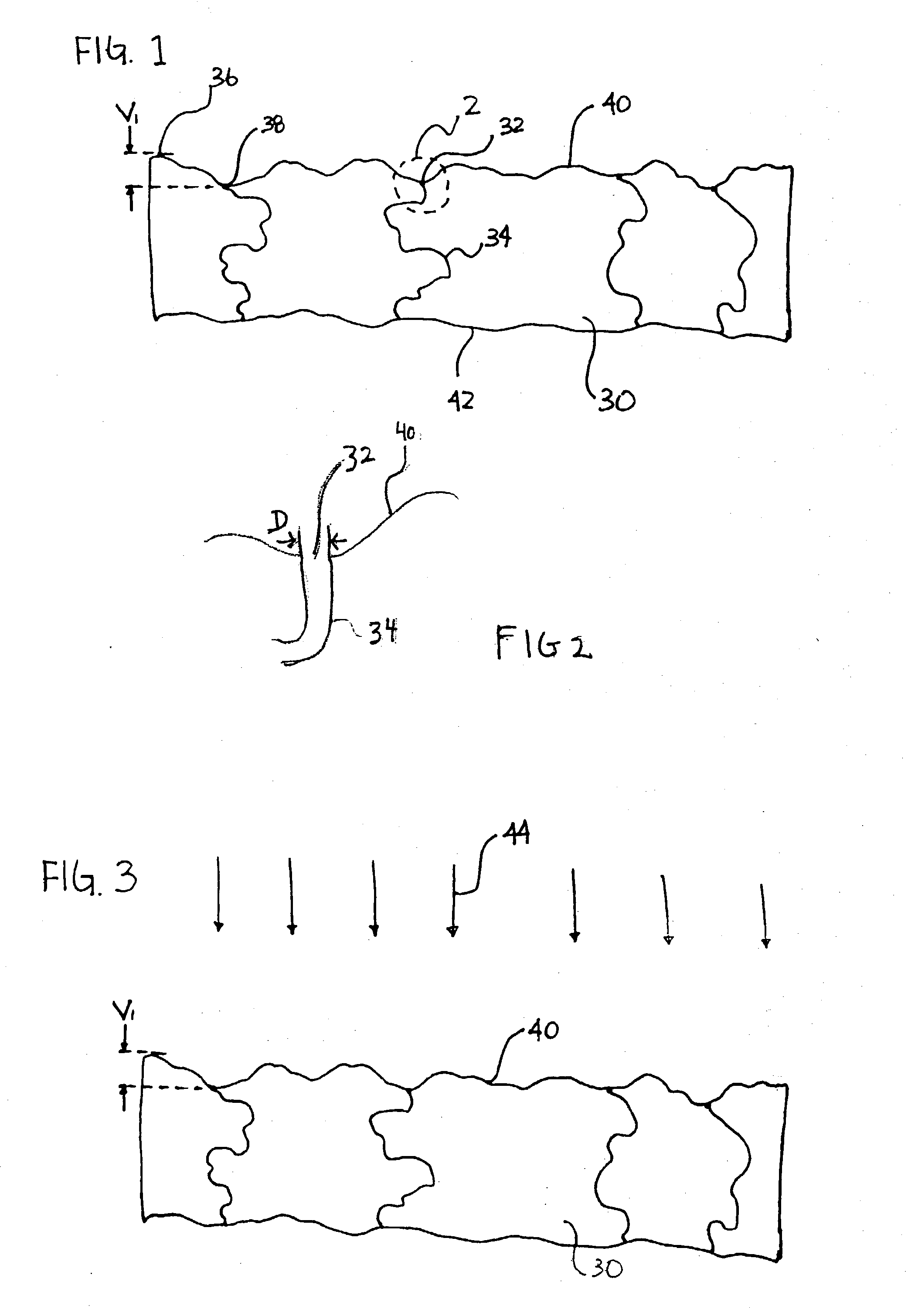
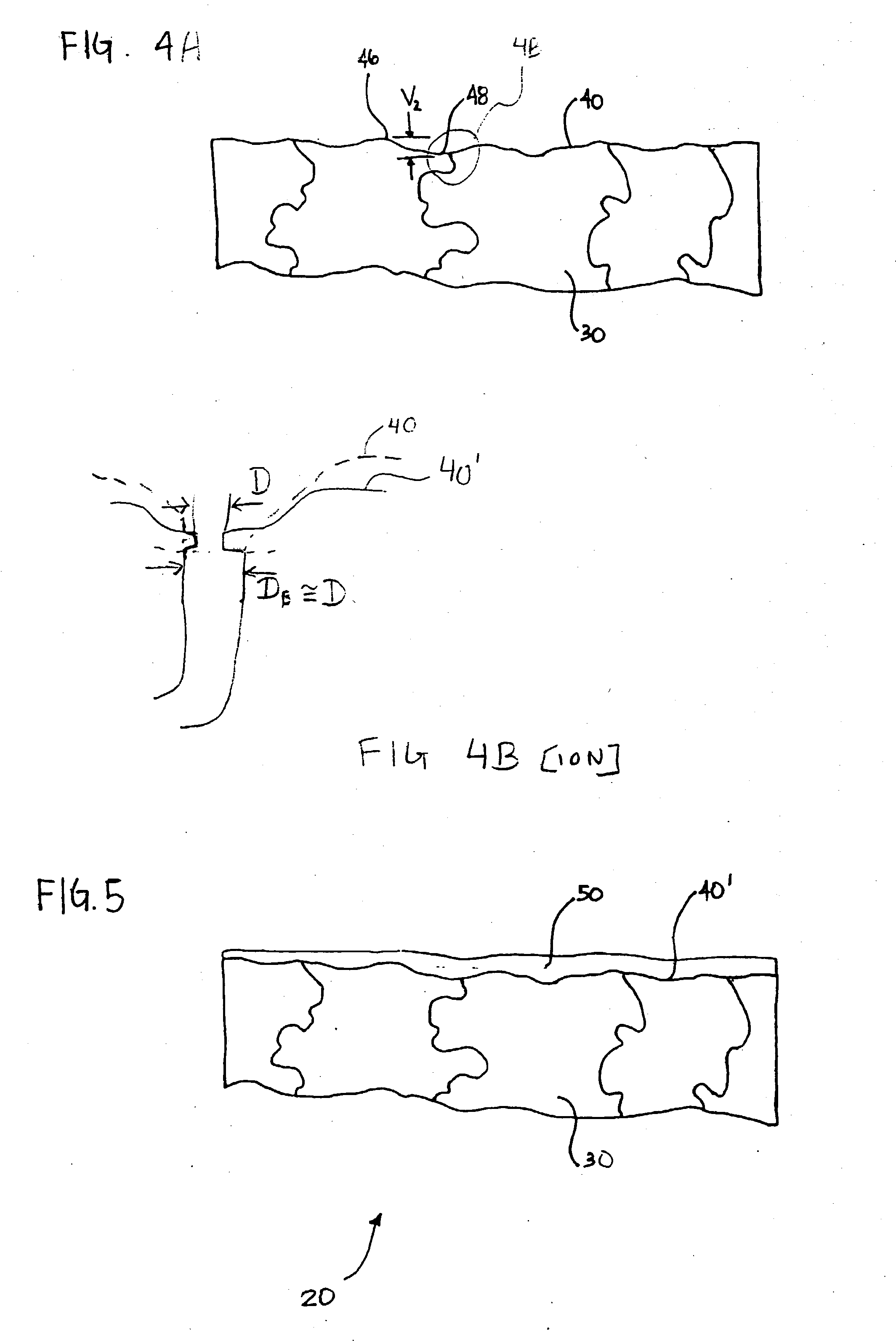
[0046] FIG. 6 shows an scanning electron microscopy ("SEM") picture of an untreated stainless steel porous metal substrate 30 with an average pore size diameter D of 20 microns and a porosity of about 46 percent. FIG. 7 shows an SEM picture of the same metal substrate 30 shown in FIG. 6 after pulse ion beam treatment, and FIG. 8 shows an SEM picture of the same metal substrate 30 shown in FIG. 6 after shot peening. Shot peening does not yield a metal substrate 30 with as smooth a surface as the ion beam treated metal substrate 30 shown in FIG. 7. The shot peened surface appears more pitted and rough when compared to the untreated metal substrate 30 of FIG. 6. The SEM picture in FIG. 7 of the pulse ion beam treated metal substrate 30 shows that this treatment resulted in a relatively smooth surface.

[0047] Although the invention has been described and illustrated with reference to specific illustrative embodiments thereof, it is not intended that the invention be limited to those illu...


PUM

PropertyMeasurementUnit
Fractionaaaaaaaaaa
Pore sizeaaaaaaaaaa
Pore sizeaaaaaaaaaa

Abstract

A method for reducing the surface variance of a porous metal substrate. The method does not significantly reduce the bulk porosity. The method can be used to reduce the surface pore diameter. A membrane, can be deposited on the reduced variance surface to form a separation membrane.

Description

[0001] Not applicable.[0002] Not applicable.INCORPORATION-BY-REFERENCE OF MATERIAL SUBMITTED ON A COMPACT DISC.[0003] Not applicable.[0004] 1. Field of the Invention[0005] This invention relates generally to the surface modification of substrates, and in particular, to a the surface modification of porous metal substrates, to receive a membrane, using an ion beam.[0006] 2. Description of Related Art[0007] The growing popularity of portable electronic devices has produced an increased demand for compact and correspondingly portable electrical power sources to energize these devices. Developments in robotics and other emerging technology applications are further increasing the demand for small, independent power sources. At present, storage or rechargeable batteries are typically used to provide independent electrical power sources for portable devices. However, the amount of energy that can be stored in storage or rechargeable batteries is insufficient to meet the need of certain app...

Claims


Application Information

Patent Timeline
IPC IPC(8): B01D53/22B01D67/00B01D69/10B01D71/02C01B3/50
CPCB01D53/228B01D67/0069B01D67/009B01D69/10B01D71/022B01D2325/04Y10T428/12479C01B2203/0405C01B2203/047C01B2203/0475C01B2203/048Y10S55/05C01B3/503B01D71/02231
Inventor CHELLAPPA, ANANDCALL, CHARLESPOWELL
Owner INTELLIGENT ENERGY INC
Learn More