

Methods and compositions for directed microwave chemistry
- Summary
- Abstract
- Description
- Claims
- Application Information
AI Technical Summary
Benefits of technology
Problems solved by technology
Method used
Image

Examples
example 2
[0230] Microwave Detection in an Immunoassay Using Isoluminol-Labeled Antibody
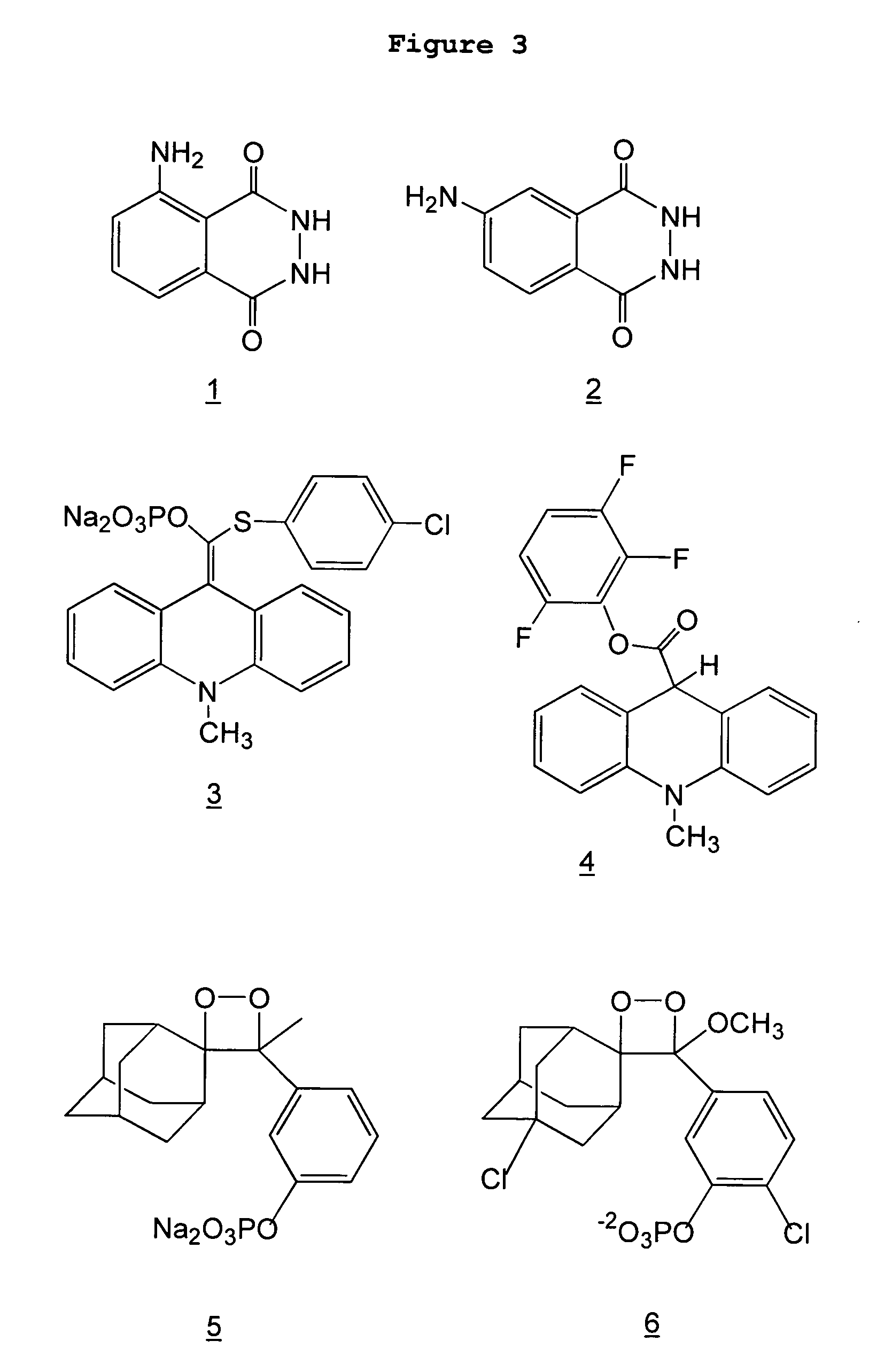
[0231] Example 1 showed that small amounts of (iso)luminol (2, FIG. 3)could be detected using microwave directed chemiluminescence. An experiment was carried out to see if microwave directed chemiluminescence could be used to detect an analyte in an immunoassay. Another purpose of the experiment was to see if a direct-labeled (isoluminol) antibody could be used.
[0232] In the experiment, mouse IgG (Sigma I-5381) was used as the analyte. Mouse IgG (1 mg / mL) was spotted (3-5 nL) on a chip (FAST Slide) in S&S Array Buffer. Analyte was detected using streptavidin-isoluminol (3.5 labels per streptavidin, Sigma S-8532) that was bound to the recognition antibody, which was a biotin goat anti-mouse antibody (Sigma B-7151). Chemiluminescence of chips (BSR-1 dielectric undercoated FAST Slides) was measured on X-ray film following spraying with reagent (see Example 1) at room temperature or upon microwaving.
[0233] Det...
example 3
[0237] Microwave Detection of Chemiluminescent Enzyme Substrates Having discovered that (iso)luminol can be used in microwave chemiluminescence analyses, experiments were conducted to determine if other chemiluminescent chemistries were also amenable to microwave triggering. Chemiluminescent compounds can often be used as direct labels (attached to proteins or nucleic acids) or enzyme substrates. Streptavidin-isoluminol is an example of the former and luminol (an HRP substrate) is an example of the latter. Enzyme substrate chemiluminescent compounds have the advantage of catalytic amplification, but they also have the drawback of light emission being a sustained low glow. Chemiluminescent enzyme substrates usually follow the pathway shown below;
E+S.fwdarw.E+P*.fwdarw.E+P+hv
[0238] where E is enzyme, S is substrate, P* is a transient product, P is final product, and hv is light emission. Metastable product P* spontaneously breaks down to form P and light. Thus, if enzyme catalysis is ...
example 4
[0246] Enzyme-Amplified Microwave Detection of Chemiluminescent Compounds
[0247] The results of Example 3 showed that APS-5 and PS-3 chemiluminescence can be detected in the absence of enzymes and that the intensity of this non-enzymatic chemiluminescence is greatly enhanced by directed microwave heating. Next, experiments were conducted to determine if enzyme-catalyzed luminol, APS-5, LPP, PS-3 and CDP-Star could be adapted to directed microwave-enhanced detection. Because these substrates are designed to emit light upon enzymatic catalysis, it was important to find conditions whereby enzyme catalysis (S.fwdarw.P* in Example 3) and light emission (P*.fwdarw.P+hv) could be aecoupled--in other words, conditions in which catalytic conversion of substrate to metastable product is rapid, but subsequent conversion to final product (P) and light was minimal. The second step (P*.fwdarw.P+hv) would then be triggered by directed microwave heating. If this were possible, then microwaves would ...
PUM
| Property | Measurement | Unit |
|---|---|---|
| Wavelength | aaaaa | aaaaa |
| Wavelength | aaaaa | aaaaa |
| Responsivity | aaaaa | aaaaa |
Abstract
Description
Claims
Application Information