Clock and data recovery circuit

a clock and data recovery technology, applied in the field of clock and data recovery circuits, can solve the problems of increasing power consumption, increasing chip size and power consumption, etc., and achieve the effects of increasing chip size, increasing power consumption, and increasing chip siz

Active Publication Date: 2004-12-16
RENESAS ELECTRONICS CORP
View PDF3 Cites 69 Cited by
  • Summary
  • Abstract
  • Description
  • Claims
  • Application Information

AI Technical Summary

Benefits of technology

0016] The clock and data recovery circuit having the frequency tracking loop including the charge pump 214, loop filter 215, and VCO 216 can be configured to track frequency modulation exceeding 0.5%. However, when the clock and data recovery circuit is made to have a multi-channel configuration, the chip size and power consumption increases. It means that when the clock and data recovery circuit having the frequency tracking loop including the charge pump, loop filter, and VCO (voltage controlled oscillator) is made to have the multi-channel configuration, all channels will be equipped with frequency tracking loops each including the charge pump, loop filter, and VCO, thereby increasing the chip size. Then, if high-speed VCOs are provided for all channels in a high-speed system of 1 Gbps or higher, for example, power consumption will increase.
0017] Accordingly, it is an object of the present invention to provide

Problems solved by technology

However, when the clock and data recovery circuit is made to have a multi-channel configuration, the chip size and power consumption increases.

Method used


Image

  • Clock and data recovery circuit
  • Clock and data recovery circuit
  • Clock and data recovery circuit

Examples


Embodiment Construction

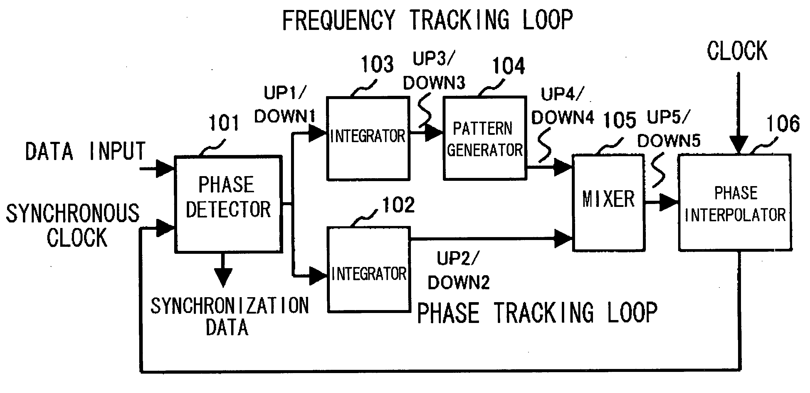
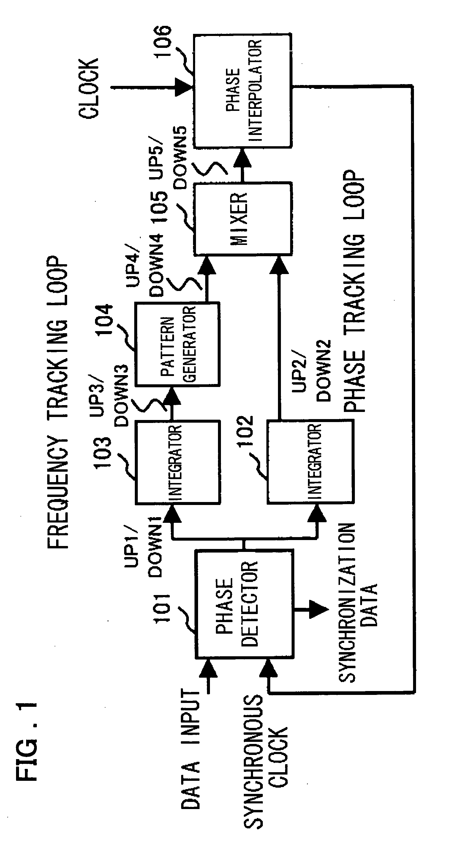
[0048] Embodiment modes of the present invention will be described. A device according to a preferred embodiment of the present invention includes a phase detector (101), a first integrator (102), a second integrator (103), a pattern generator (104), a mixer (105), and a phase interpolator (106). The phase detector (101) receives a data signal and a synchronous clock signal, detects a delay or an advance between the phases of the two input signals, and then outputs a first control signal (UP1 / DOWN1), according to the result of detection. The first integrator (102) integrates the first control signal output from the phase detector (101) to output a second control signal (UP2 / DOWN2). The second integrator (103) integrates the first control signal (UP1 / DOWN1) output from the phase detector (101) to output a third control signal. The pattern generator (104) inputs the third control signal (UP3 / DOWN3) from the second integrator (103) and then outputs a fourth control signal. The mixer (1...


PUM


Abstract

A clock and data recovery circuit, for tracking frequency-modulated input data, comprises a phase detector for receiving a data signal and a synchronous clock signal, detecting a phase delay or a phase advance, and outputting an UP1/DOWN1 signal, first and second integrators for integrating the UP1/DOWN1 signal and outputting an UP2/DOWN2 signal and an UP3/DOWN3 signal, respectively, a pattern generator for receiving the UP3/DOWN3 signal from the second integrator to output an UP4/DOWN4 signal, a mixer for receiving the UP2/DOWN2 signal from the first integrator and the UP4/DOWN4 signal from the pattern generator and generating an UP5/DOWN5 signal for output, and a phase interpolator for interpolating the phase of an input clock signal based on the UP5/DOWN5 signal from the mixer, for output are provided. A clock signal output from the interpolator is fed back to the phase detector as the clock.

Description

[0001] The present invention relates to a clock and data recovery circuit for generating a clock signal and data from input data.[0002] When a clock generator in an electronic device generates a single frequency, emission increases due to the frequency and harmonics. Thus, a spread spectrum clock signal for reducing electromagnetic interference by performing frequency modulation and thereby reducing peaks of unwanted emissions is employed. As an approach for extracting a clock signal from serial data frequency modulated using the spread spectrum clock, a clock and data recovery circuit as shown in FIG. 13 is known (refer to Non-patent Document 1, for example).[0003] Referring to FIG. 13, in addition to a phase tracking loop constituted from a phase detector 201, an integrator 202, and a phase interpolator 206, a frequency tracking loop constituted from an integrator 203, a charge pump 214, a loop filter 215, a VCO (voltage controlled oscillator) 216, and the phase interpolator 206 i...

Claims


Application Information

Patent Timeline
IPC IPC(8): H03L7/08H03D13/00H03K5/15H03L7/06H03L7/081H03L7/089H03L7/093H03L7/107H03L7/113H04L7/033
CPCH03D13/004H03L7/0814H03L7/093H03L7/107H04L7/0025H04L7/0337H03K5/15H03L7/089
Inventor AOYAMA, MORISHIGE
Owner RENESAS ELECTRONICS CORP
Why Eureka
Try Eureka