Optoelectronic displays

a technology of optoelectronic display and display device, which is applied in the direction of identification means, tubes with screens, instruments, etc., can solve the problems of lcd display slowness, research, and a number of problems,

Inactive Publication Date: 2004-12-30
CAMBRIDGE DISPLAY TECH LTD
View PDF14 Cites 39 Cited by
  • Summary
  • Abstract
  • Description
  • Claims
  • Application Information

AI Technical Summary

Problems solved by technology

However despite their popularity LCD displays still suffer from a number of problems which, even after many years of research, have not been fully overcome.
Thus generally speaking LCD displays are relatively slow, with switching times of the order of milliseconds, and have a relatively limited viewing angle.
LCDs displays can also suffer from viewing artefacts such as display inversion at certain viewing angles, and have a relatively unexciting visual appearance as compared with emissive display technologies.
Furthermore since LCD displays are passive displays operating by blocking either transmitted or reflected light they have an upper efficiency limit which is reduced in colour displays by the need for coloured filters.
Known emissive display technologies include cathode ray tubes, plasma display panels, thin film electro-luminescent displays, and organic light emitting diodes (OLEDs), but a general problem with emissive displays is their relatively high power consumption which makes them unsuitable for many applications, and in particular, for many portable applications.
Suitable structures include conventional OLED structures and the electric field necessary to quench the photoluminescence can be applied to the photo-(or electro-)luminescent material simply by reverse biassing the OLED device, although this photoluminescence quenching effect is difficult to observe under ordinary circumstances.
However none of these prior art documents discloses a display based upon the photoluminescence quenching principle or the use of photoluminescence quenching to provide a display.

Method used


Image

  • Optoelectronic displays
  • Optoelectronic displays
  • Optoelectronic displays

Examples


Embodiment Construction

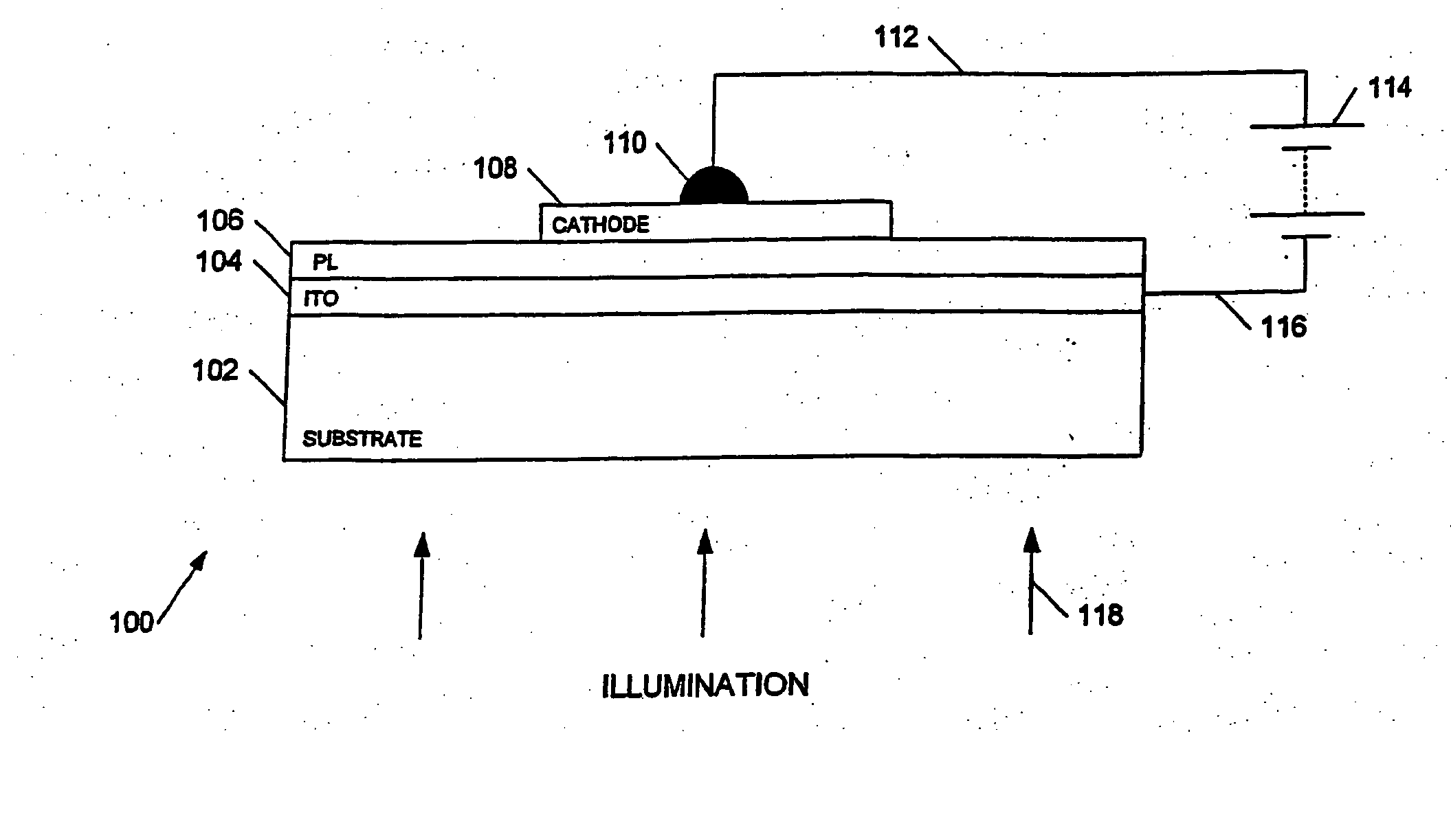
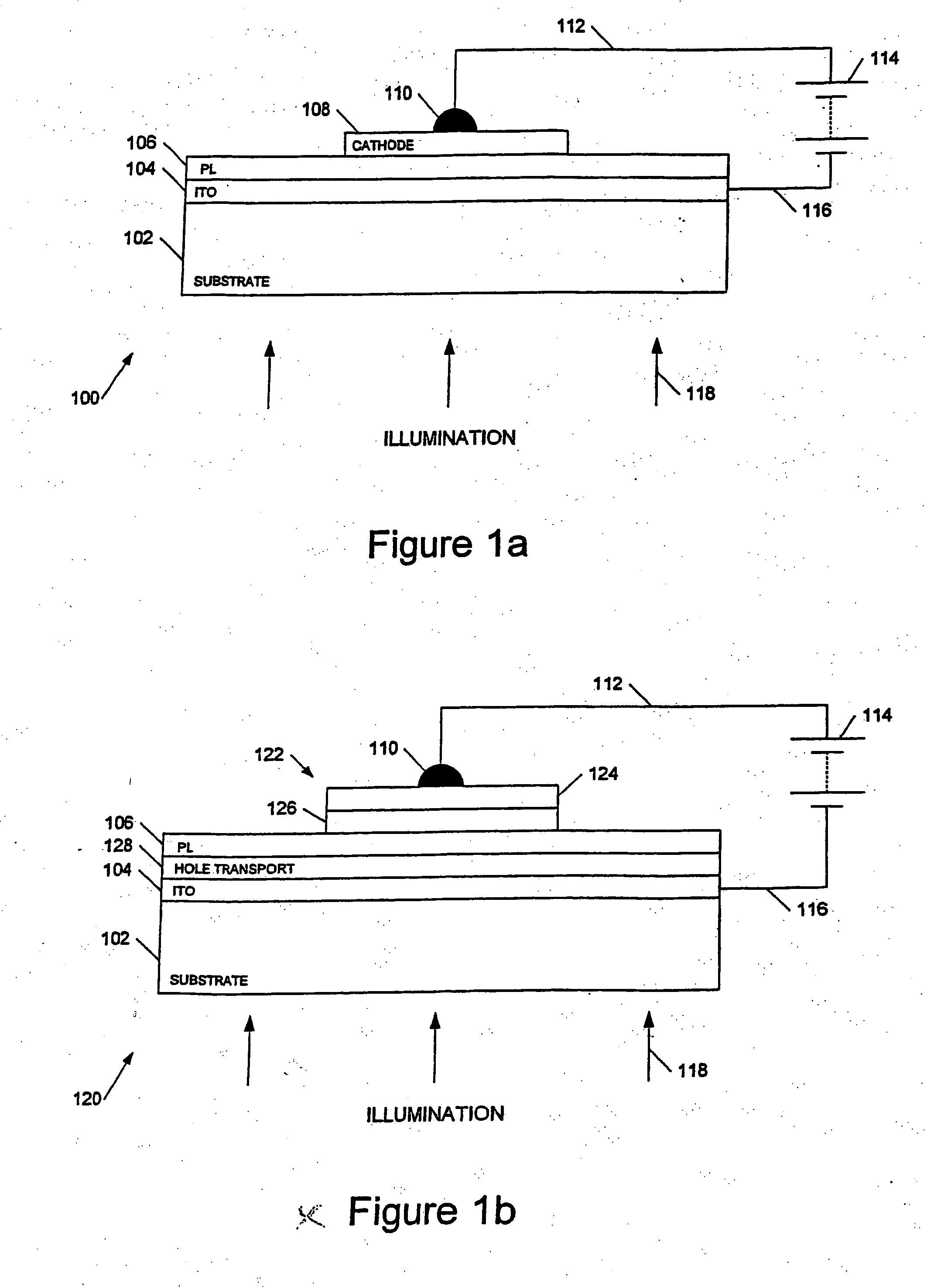
[0132] The results from two exemplary devices will be presented. The is comprised an 80:20 polymer blend of F8BT:TFB with a two layer calcium / aluminium cathode. The second comprised a 79:20:1 polymer blend of F8BT:TFB:poly(2,7-(9,9-di-n-octylfluorene)-co-(2,5-thienylene-3,6-benz-othiadiazole-2,5-thienylene) with a three layer cathode of lithium fluoride / calcium / aluminium. Both devices photoluminesced in the yellow and had an intrinsic yellow colouration.

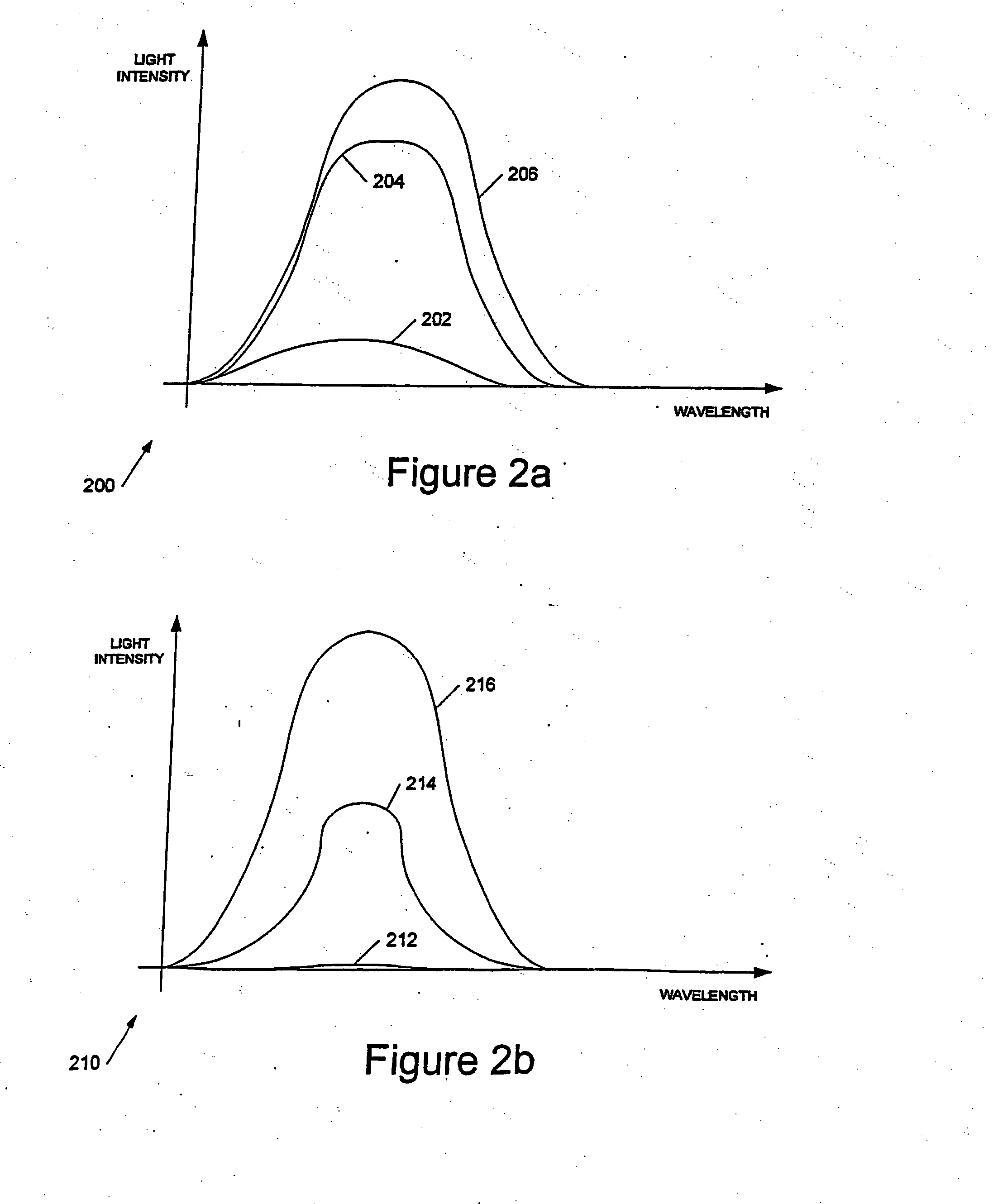
[0133] FIGS. 8a and 8b show the variation of photoluminescent emission with reverse bias for the first and second devices respectively. In each case the devices were excited using light having a wavelength of 466 mm, from monochromator 706, and filter 718 and photodiode 720 were arranged to collect light of a wavelength longer than 570 nm.

[0134] The two graphs have been normalised to a maximum 100% photoluminescence level at zero applied bias.

[0135] The two graphs show that with a reverse bias voltage of around 20 volts the photolumi...


PUM

PropertyMeasurementUnit
Electrical conductivityaaaaaaaaaa
Coloraaaaaaaaaa
Concentrationaaaaaaaaaa

Abstract

Apparatus and methods for providing displays based upon the principle of photoluminescent quenching are described. The invention includes a method of displaying information using photoluminescence quenching, the method comprising providing an optoelectronic display comprising a photoluminescent material between a pair of electrodes, providing illumination for the photoluminescent material to cause the photoluminescent material to photoluminescence, and biasing the electrodes to at least partially quench the photoluminescence.

Description

[0001] This invention generally relates to displays and display drivers, and more particularly to apparatus and methods for providing displays based upon the principle of photoluminescence quenching.BACKGROUND TO THE INVENTION[0002] A broad range of optoelectronic display devices is known, ranging from incandescent lamps and light emitting diodes through to liquid crystal and plasma displays and cathode ray tubes. A particularly important category of displays is pixellated displays and, for low power applications, liquid crystal displays, (LCDs) are generally the technology of choice. Known LCD displays operate in transmissive mode, for example using a back light, reflective mode, for example illuminated by daylight, and transflective mode in which the pixels have both reflective and transmissive elements. However despite their popularity LCD displays still suffer from a number of problems which, even after many years of research, have not been fully overcome. Thus generally speakin...

Claims


Application Information

Patent Timeline
IPC IPC(8): G09G3/32H01L27/32G09F9/30H01L51/00H01L51/30H01L51/40H01L51/50H01L51/52
CPCG09G3/3225G09G2300/046G09G2300/0842H01L27/3211H01L27/3244H01L51/0004H01L51/0037H01L51/0038H01L51/0043H01L51/0081H01L51/5036H01L51/5262H10K59/35H10K59/12H10K71/13H10K85/1135H10K85/114H10K85/151H10K85/324H10K50/125H10K50/85H05B33/00
Inventor SMITH, EUAN CHRISTOPHERGUNNER, ALEC GORDONHALLS, JONATHAN J. M.
Owner CAMBRIDGE DISPLAY TECH LTD
Why Eureka
Try Eureka