Radiation and melt treated ultra high molecular weight polyethylene prosthetic devices
- Summary
- Abstract
- Description
- Claims
- Application Information
AI Technical Summary
Benefits of technology
Problems solved by technology
Method used
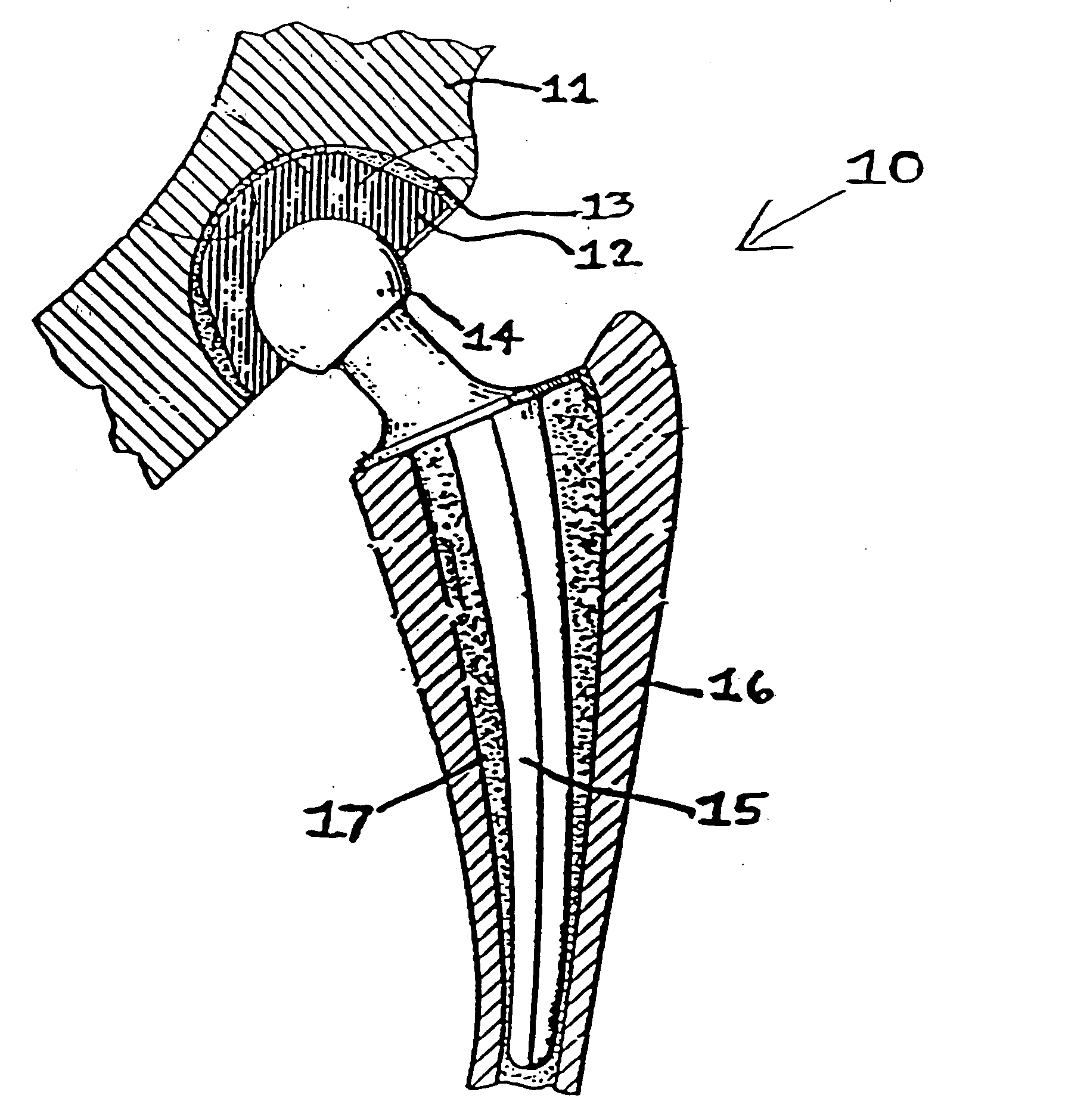
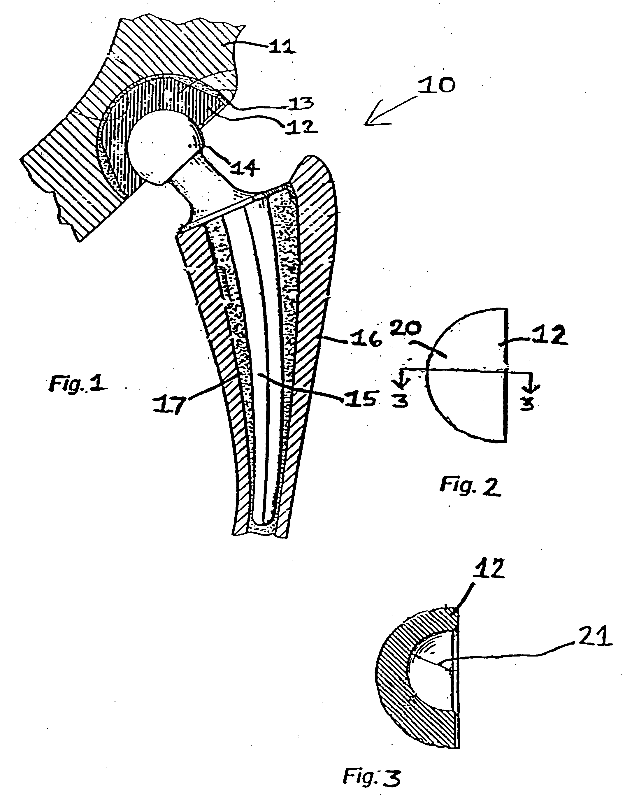
Image

Examples
example 1
Method of Making Melt-Irradiated UHMWPE (MIR)
This example illustrates electron irradiation of melted UHMWPE.
A cuboidal specimen (puck) of size 10 mm×12 mm×60 mm, prepared from conventional ram extruded UHMWPE bar stock (Hoescht Celanese GUR 415 bar stock obtained from Westlake Plastics, Lenni, Pa.) was placed in a chamber. The atmosphere within the chamber consisted of low oxygen nitrogen gas (<0.5 ppm oxygen gas) (obtained from AIRCO, Murray Hill, N.J.). The pressure in the chamber was approximately 1 atm. The temperature of the sample and the irradiation chamber was controlled using a heater, a variac and a thermocouple readout (manual) or temperature controller (automatic). The chamber was heated with a 270 W heating mantle. The chamber was heated (controlled by the variac) at a rate such that the steady state temperature of the sample was about 175° C. The sample was held at the steady state temperature for 30 minutes before starting the irradiation.
Irradiation was do...
example 2
Comparison of Properties of GUR 415 UHMWPE Bar Stock and Melt-Irradiated (MIR) GUR 415 UHMWPE Bar Stock (20 MRad)
This example illustrates various properties of the irradiated and unirradiated samples of UHMWPE bar stock (GUR 415) obtained from Example 1. The tested samples were as follows: the test sample was bar stock which was molten and then irradiated while molten; control was bar stock (no heating / melting, no irradiation).
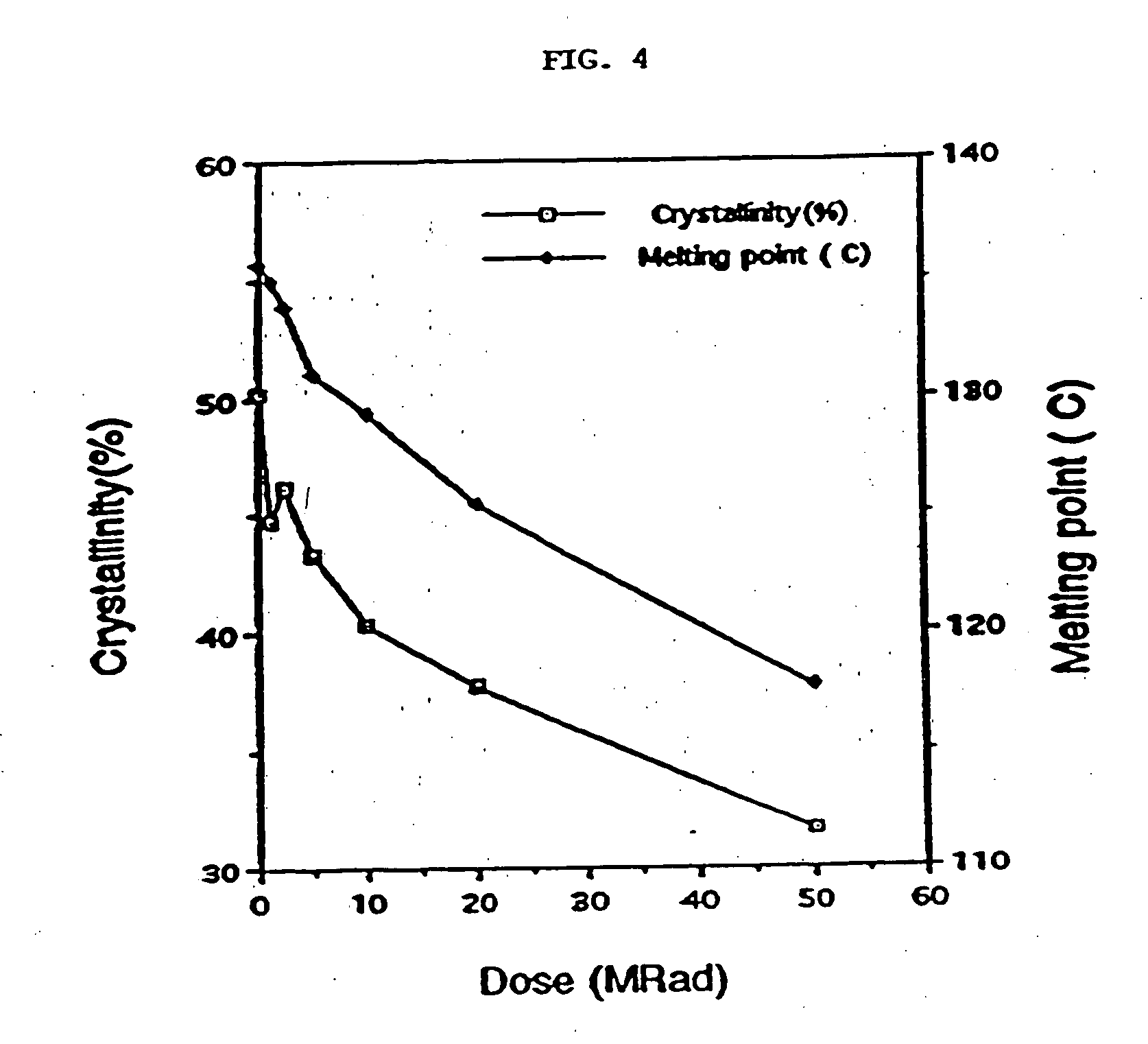
(A) Differential Scanning Calorimetry (DSC)
A Perkin-Elmer DSC7 was used with an ice-water heat sink and a heating and cooling rate of 10° C. / minute with a continuous nitrogen purge. The crystallinity of the samples obtained from Example 1 was calculated from the weight of the sample and the heat of melting of polyethylene crystals (69.2 cal / g). The temperature corresponding to the peak of the endotherm was taken as the melting point. The lamellar thickness was calculated by assuming a lamellar crystalline morphology, and knowing ΔH° the heat of melting o...
example 3
Method of Making Melt-Irradiated (MIR) UHMWPE Conventional Articular Cups
This example illustrates electron irradiation of a melted UHMWPE conventional articular cup.
A conventional articular cup (high conformity unsterilized UHMWPE cup made by Zimmer, Inc., Warsaw, Ind.) of internal diameter 26 mm and made of GUR 415 ram extruded bar stock, was irradiated under controlled atmosphere and temperature conditions in an air-tight chamber with a titanium cup holder at the base and a thin stainless steel foil (0.001 inches thick) at the top. The atmosphere within this chamber consisted of low oxygen nitrogen gas (<0.5 ppm oxygen gas) (obtained from AIRCO, Murray Hill, N.H.). The pressure in the chamber was approximately 1 atm. The chamber was heated using a 270 W heating mantle at the base of the chamber which was controlled using a temperature controller and a variac. The chamber was heated such that the temperature at the top surface of the cup rose at approximately 1.5° to 2° C....
PUM
| Property | Measurement | Unit |
|---|---|---|
| Temperature | aaaaa | aaaaa |
| Melting point | aaaaa | aaaaa |
| Temperature | aaaaa | aaaaa |
Abstract
Description
Claims
Application Information
 - Generate Ideas
- Intellectual Property
- Life Sciences
- Materials
- Tech Scout
- Unparalleled Data Quality
- Higher Quality Content
- 60% Fewer Hallucinations
Browse by: Latest US Patents, China's latest patents, Technical Efficacy Thesaurus, Application Domain, Technology Topic, Popular Technical Reports.
© 2025 PatSnap. All rights reserved.Legal|Privacy policy|Modern Slavery Act Transparency Statement|Sitemap|About US| Contact US: help@patsnap.com